Rittal fan-and-filter unit assembly and operating instructions 19
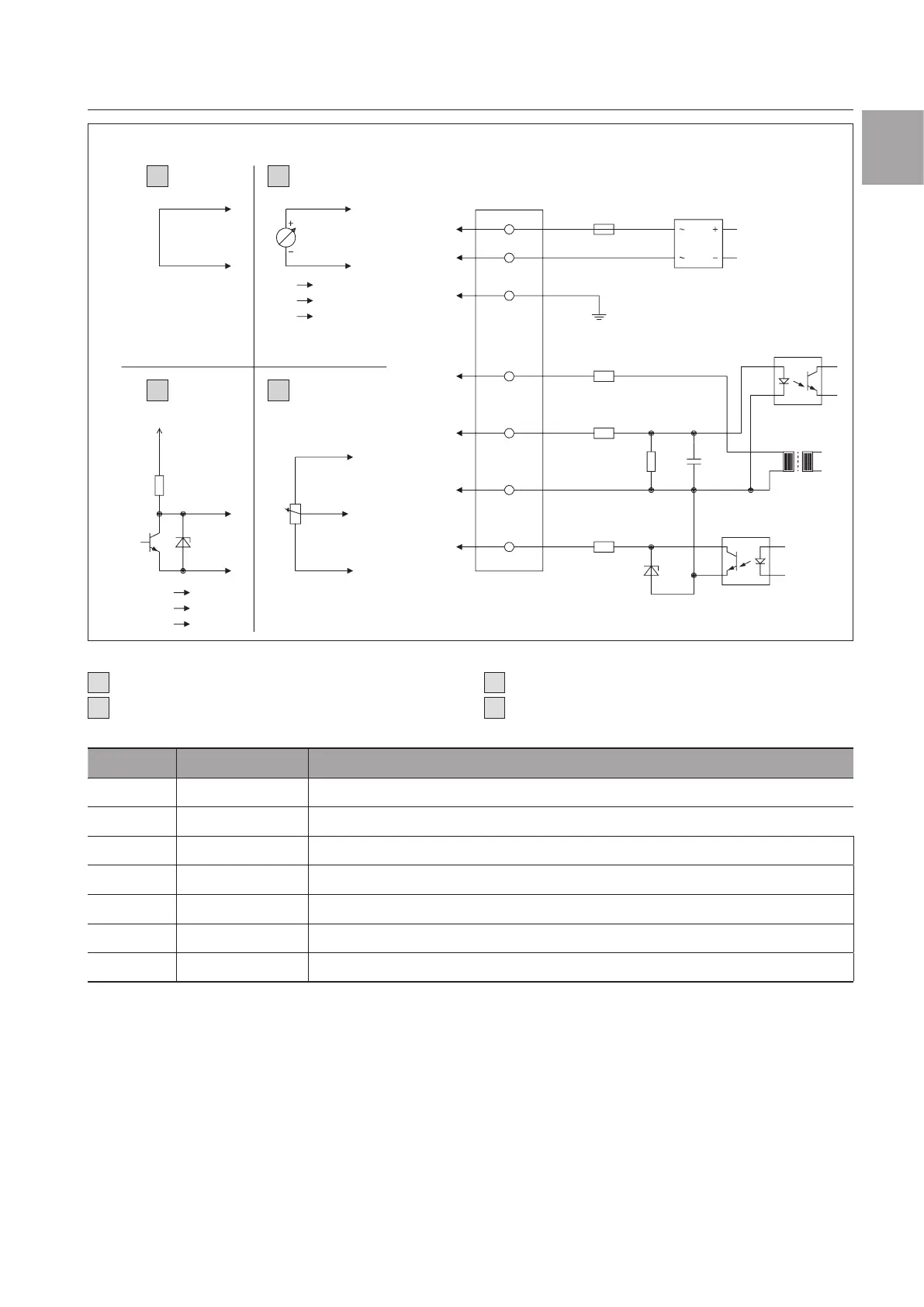
Connection diagrams
EN
CON10
CON11
CON12
L
N
PE
+10 V
10 V/PWM
GND
Speed
PE 1
I max. = 1.1 mA
I max. = 10 mA
47 k
680 R
ZMM 47
47 k
1 uF
1.6 AT
AC 1
AC 2
P
3
1
2
3
4
3
2
1
3
2
3
2
2
1
10 K
1
2
12 V
15 V
100 % PWM n = max.
10 % PWM n = min.
<10 % PWM n =
0
1
4
1
N
1 – 10 V
10 V n = max.
1 V n = min.
<1 V n = 0
1 2
3 4
For SK 3245 only!
Interface Fan/motor
Fig.14: Connection diagram 3245
1
Max. speed (as delivered)
2
Adjustable speed
3
Adjustable speed via PWM 1 – 10 kHz
4
Adjustable speed via potentiometer
No. Connection Function/Assignment
CON10 L Power supply 200…240 V AC, 50…60 Hz
CON11 N Neutral conductor
CON12 PE PE conductor
1 GND GND connection of the control interface
2 0…10V/PWM Control input 0…10 V or PWM, galvanically isolated, impedance 100 kΩ
3 +10 V Voltage output 10 V max. 1.1 mA, galvanically isolated, not short circuit-protected
4 Speed Speed output Open Collector, 1 pulse per revolution, galvanically isolated
Tab. 15: Explanations to fig.14