8 Rittal CMC III online comfort handle VX
5 Installation
EN
5 Installation
5.1 Safety instructions
◾ Please observe the valid regulations for installation
in the country in which the comfort handle is in-
stalled and operated, and the national regulations for
accident prevention. Please also observe any internal
company regulations, such as work, operating and
safety regulations.
◾ The technical specifications and limit values stated
must not be exceeded under any circumstances. In
particular, this applies to the specified ambient tem-
perature range and IP degree of protection.
◾ If a higher IP protection class is required for a special
application, the transponder reader must be installed
in an appropriate housing or in an appropriate enclo-
sure with the required IP degree of protection.
5.2 Siting location requirements
To ensure the unit functions correctly, the conditions
for the installation site of the unit specified in section8
"Technical specifications" must be observed.
Electromagnetic interference
– Interfering electrical installations (high frequency)
should be avoided.
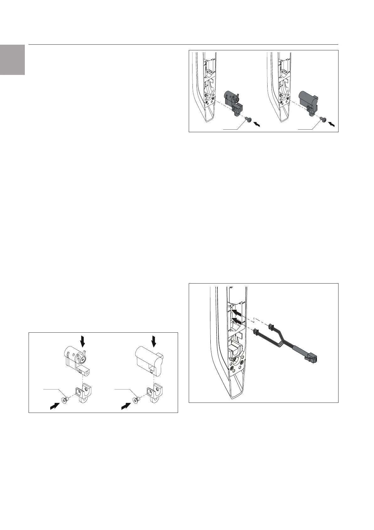
5.3 Installation of lock insert
A lock insert no. 3524 E or 40 mm profile half-cylinder
to DIN 18 252 may be used in the comfort handle as
an alternative access option for the enclosure. This
allows the handle to be opened manually and inde-
pendently of the electrical activation.
◾ Fit the lock insert or profile half-cylinder in the holder
included with the supply of the comfort handle (fig.2,
M
A
= 2+1Nm).
M5x8M5x8
Fig.2: Fit the lock insert (left) or profile half-cylinder (right) in
the holder
◾ Then mount the recess with the lock insert or profile
half-cylinder in the comfort handle (fig.3, M
A
=
2+1Nm).
4x16 4x16
Fig.3: Mount the holder with the lock insert (left) or profile
half-cylinder (right) in the comfort handle
5.4 Installation procedure
There are generally several options for installing the
comfort handle:
– Installation on a VX and VX IT sheet steel door
– Installation on a VX glazed door
– Installation on a VX IT glazed door or VX IT vented
door
5.4.1 Installation notes
◾ Cover the area around where holes are to be drilled
before drilling in order to prevent damage and
scratches.
◾ Connect the connection cables to the comfort handle
so that the connector with the long cables is in the
bottom jack and the connector with the short cables
is in the top jack (see fig.4).
Fig.4: Connecting the cable to the comfort handle
5.4.2 Installation on a VX and VX IT sheet steel
door
The installation is performed directly on the frame of a
VX and VX IT sheet steel door.
◾ Drill suitably sized holes in the required position in the
sheet steel door, depending on the position of the
hinge (fig.5).