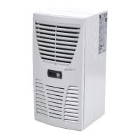
Do you have a question about the Rittal SK 3328. series and is the answer not in the manual?
Describes the two sets of instructions provided for the unit.
Mentions the declaration of conformity supplied separately.
States that instructions are integral to the product and must be given to the operator.
Explains the meaning of symbols for instructed actions and safety warnings.
Explains the purpose and principle of enclosure cooling units.
Describes the refrigeration system components and cycle.
Mentions the controller for setting cooling unit functions.
Explains serial unit interface for connecting multiple cooling units.
Details safety features like pressure-operated switch and thermal winding shields.
Explains condensation formation and automatic evaporation.
Discusses filter mats for condenser protection and monitoring.
Describes the function and connection of an optional door limit switch.
Mentions an optional interface card for higher-level monitoring.
Guidelines for selecting a suitable installation location.
General instructions for checking packaging and enclosure sealing.
Advice on arranging components to prevent condensation and air short-circuits.
Describes external, partial, and full internal mounting options.
Instructions for cutting openings in the enclosure based on templates.
Steps for attaching the unit externally using sealing tape and screws.
How to mount the unit partially inside the enclosure.
Detailed steps for fully mounting the unit inside the enclosure.
Instructions for connecting the condensate drain hose.
General notes on electrical installation and regulations.
Requirements for voltage, frequency, and mains connection.
Guidance on overvoltage protection and supply line capacity.
Specific notes for three-phase unit installation.
Details on connecting and using the door limit switch.
Information regarding flicker limits and potential mitigation.
Recommendation for potential equalisation connection.
General steps for electrical installation.
How to connect multiple cooling units in a bus system.
Usage of interface card X3 for monitoring and integration.
Completing electrical installation following wiring plans.
Steps to complete the physical assembly before operation.
Instructions for installing filter mats into the louvred grille.
Steps for connecting the display and attaching the louvred grille.
Explains the function and setting of the filter mat monitor.
How to operate the cooling unit using the Basic controller.
Lists features and supported voltage variants of the Basic controller.
Explains the LED indicators for operating and error status on the Basic controller.
Instructions to activate a test mode for the cooling unit.
Steps to adjust the temperature setting using the potentiometer.
Procedure to reset the Basic controller after an error.
How to operate the cooling unit using the Comfort controller.
Lists features and supported voltage variants of the Comfort controller.
Instructions to activate the test mode for the Comfort controller.
Explains how to navigate and change parameters on the Comfort controller.
Details parameters that can be edited on the Comfort controller.
Visual guide to programming the Comfort controller's parameters.
Explains system messages and how they are displayed.
How to configure master-slave units for networked operation.
Guidance on interpreting system messages from the Comfort controller.
Procedure to reset the Comfort controller after specific faults.
Overview of the cooling unit's maintenance-free design and cleaning.
Instructions for cleaning the unit using compressed air.
Exploded view and part numbers for SK 3302.xxx models.
Exploded view and part numbers for SK 3302.3xx models.
Exploded view and part numbers for SK 3303.xxx, SK 3361.xxx.
Exploded view and part numbers for SK 3304.xxx, SK 3305.xxx.
Exploded view and part numbers for SK 3328.xxx, SK 3329.xxx.
Exploded view and part numbers for SK 3332.xxx models.
Exploded view and part numbers for SK 3366.xxx, SK 3377.xxx.
Diagrams showing dimensions for external installation.
Diagrams showing dimensions for partial internal installation.
Diagrams showing dimensions for full internal installation.
| Brand | Rittal |
|---|---|
| Model | SK 3328. series |
| Category | Air Conditioner |
| Language | English |


 Loading...