Do you have a question about the Rittal SK 3384.xxx and is the answer not in the manual?
Details the two sets of instructions provided with the unit for assembly and operation.
States that the declaration of conformity is supplied as a separate document with the unit.
Emphasizes that instructions are integral to the product and must be kept accessible by the plant operator.
Explains the meaning of safety symbols like 'Danger', 'Caution', and 'Note' used in the guide.
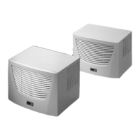
Explains the primary purpose of enclosure cooling units to dissipate heat from internal enclosure air.
Describes the controller for setting cooling unit functions, including display and extended options.
Details how to create a bus connection with up to ten cooling units using serial interface X2.
Covers pressure-operated switches, temperature monitoring, and thermal winding shields for unit protection.
Explains condensation formation and the automatic electrical condensate evaporator system.
Discusses filter options like PU foam and metal filters, and the filter mat monitor function.
Describes the optional door limit switch for deactivating the unit when the enclosure door is opened.
Mentions an optional interface card for integrating the cooling unit into higher-level monitoring systems.
Defines intended use and warns against improper application or modification of the cooling unit.
Lists the items included in the packaging unit for the cooling unit upon delivery.
Provides guidelines for selecting an appropriate location for the enclosure and cooling unit, considering ventilation and ambient conditions.
General advice on checking packaging for damage and ensuring the enclosure is sealed for IP 54 rating.
General assembly instructions, including checking packaging and ensuring enclosure sealing (IP 54).
Advises on arranging components to prevent short-circuiting airflow and ensure proper climate control.
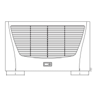
Details the mounting of the cooling unit on the enclosure roof, referencing the drilling template.
Instructions for using the drilling template to cut openings in the enclosure roof, emphasizing safety.
Steps for attaching the sealing frame and mounting the cooling unit onto the prepared enclosure roof.
Guidance on connecting the condensate discharge hose, including laying it correctly without kinks.
General warnings and requirements for electrical installation, emphasizing qualified electricians and regulations.
Specifies that mains connection data must match the rating plate and requires an all-pin isolating device.
Stresses the need for external overvoltage protection and checks on supply line capacity.
Details specific connection requirements for three-phase units, including motor circuit-breakers and phase monitoring.
Instructions for connecting the door limit switch, including cable specifications and contact behavior.
Addresses flicker limits and the need for supply impedance checks or line reactors for sensitive components.
Explains how to integrate the unit into existing potential equalization systems for EMC reasons.
General section for electrical installation procedures.
Details connecting multiple cooling units via the serial device interface X2 using a master-slave setup.
Describes connecting an optional interface card to X3 for system message evaluation and remote monitoring.
Instructions for completing the electrical installation inside the unit, referencing wiring plans.
Covers the final steps of assembly, including filter media installation and connecting the display.
Explains the function of the filter mat monitor, which detects dirt by measuring temperature difference.
Details how to operate the cooling unit using the controller on the front panel, including button functions.
Lists the supported voltage variants, functions like start-up delay, and master-slave capabilities of the controller.
Describes the energy-saving eco-mode, its activation conditions, and how it affects evaporator fan operation.
Explains how to activate a test function that runs the cooling unit independently of temperature settings for a set duration.
Provides guidance on navigating the programming interface and entering values for parameters.
Lists and explains editable parameters, including temperature setpoints, filter monitoring, and eco-mode settings.
A graphical overview illustrating the sequence of button presses for programming various parameters.
Details system messages displayed on the controller and how they can be evaluated via relays.
Instructions for configuring master and slave units in a network, including identifier assignment.
Explains how system messages are indicated by numbers and require controller reset after fault rectification.
Describes the procedure to reset the e-Comfort controller after specific fault occurrences (A03, A06, A07).
Describes the cooling circuit as maintenance-free, with fans on ball bearings, and general cleaning recommendations.
Details the process of cleaning components of the external air circuit using compressed air or a vacuum cleaner.
Provides detailed dimensional drawings and cut-out sizes required for mounting different cooling unit models.
| Brand | Rittal |
|---|---|
| Model | SK 3384.xxx |
| Category | Refrigerator |
| Language | English |