2
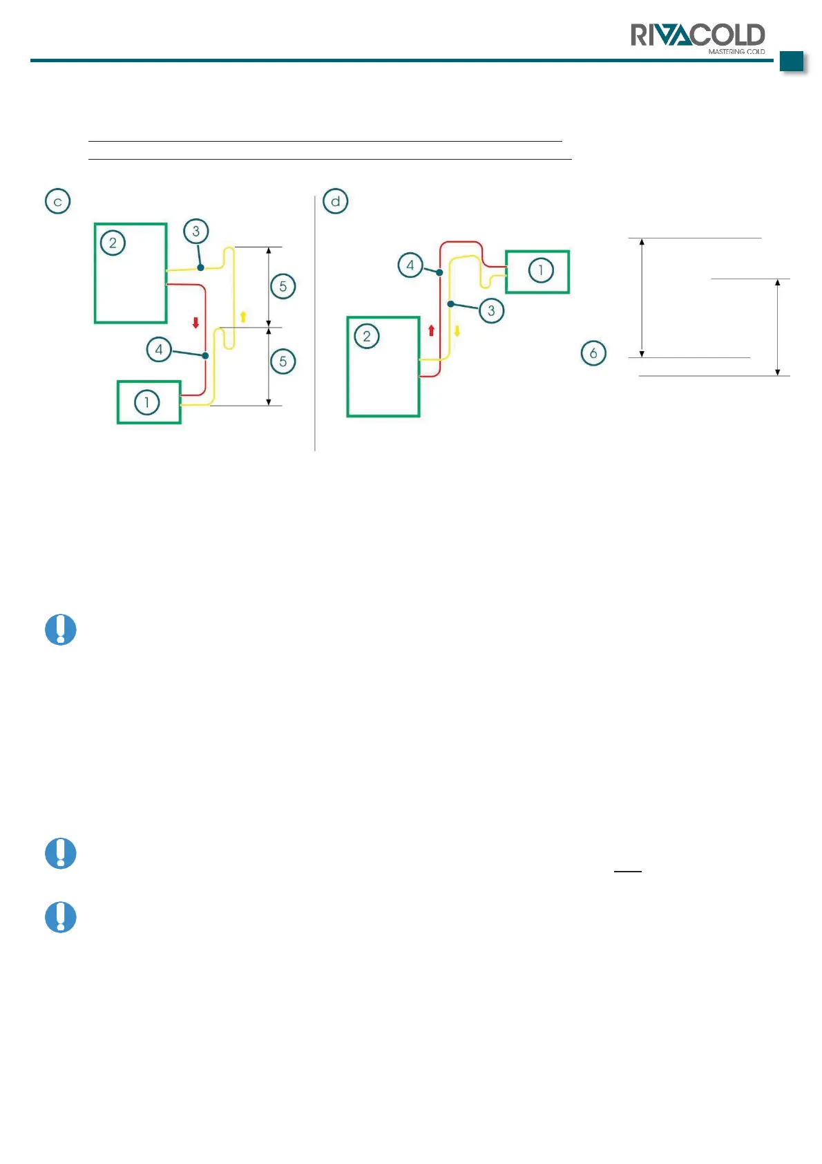
The following images show a number of explanatory notes for the installation of the described sections
in order to guarantee a correct oil return by creating siphons and slopes.
a.
Evaporator positioned at a lower level with respect to the central point
b.
Evaporator positioned at a higher level with respect to the central point
Siphons minimum distance 2÷3
IMPORTANT
In the vertical section of the pipe create siphons every 2÷3 metres.
In the horizontal section, create inclination of the piping of 2÷3%, in the flow direction of the refrigerant.
ATTENTION: The outlet pipe of the safety valve must be sized in compliance with the laws of the
country of installation.
The size of the output on the machine is valid for a linear conveyance with a maximum length of 10m.
The conveyance is necessary where it is necessary to send the gas leaving the safety valves outside of a
possible machines room.
The connections are performed in such a way that welding or brazing can be carried out according to the
type of material of the pipe being used. In general, steel requires welding, while other materials such as K65 or
copper require brazing.
ATTENTION: Machine supplied under nitrogen pressure. Before working on the connections, remove
the pressure by opening the appropriate service v
alves and acting on the pressure outlets in the
circuit. If there is no pressure in the partly-completed machine circuit, do not
contact the manufacturer.
ATTENTION: Perform preparation of the connections by making a clean cut using appropriate tools.