EasyManua.ls Logo

Rivacold CO2NNEXT - Name; Frame and Components Layout

Rivacold CO2NNEXT
59 pages
Print Icon
To Next Page IconTo Next Page
To Previous Page IconTo Previous Page
Loading...
CO
2
NNEXT
rev.01
EN
82 / 293
3.1.1.
Name
A
Series: CO2NNext with BLDC motor
B
Size of compressor(s)
C
Type of application:
M = medium temperature
(TN) L = low temperature
D
Number of fans:
1 = an electronic fan-motor 2 =
two electronic fan-motors
E
Fan-motors diameter: 450 mm
F
Refrigerant type R744
G
Progressive no.
H
No. of gas cooler/capacitor rows
I
Expansion type: with thermostat valve
L
Supply voltage:
1 = 230/1/50 + neutral
2 = 400/3/50 +
neutral
M
Optional *
*NOTE: For further information, refer to UT.
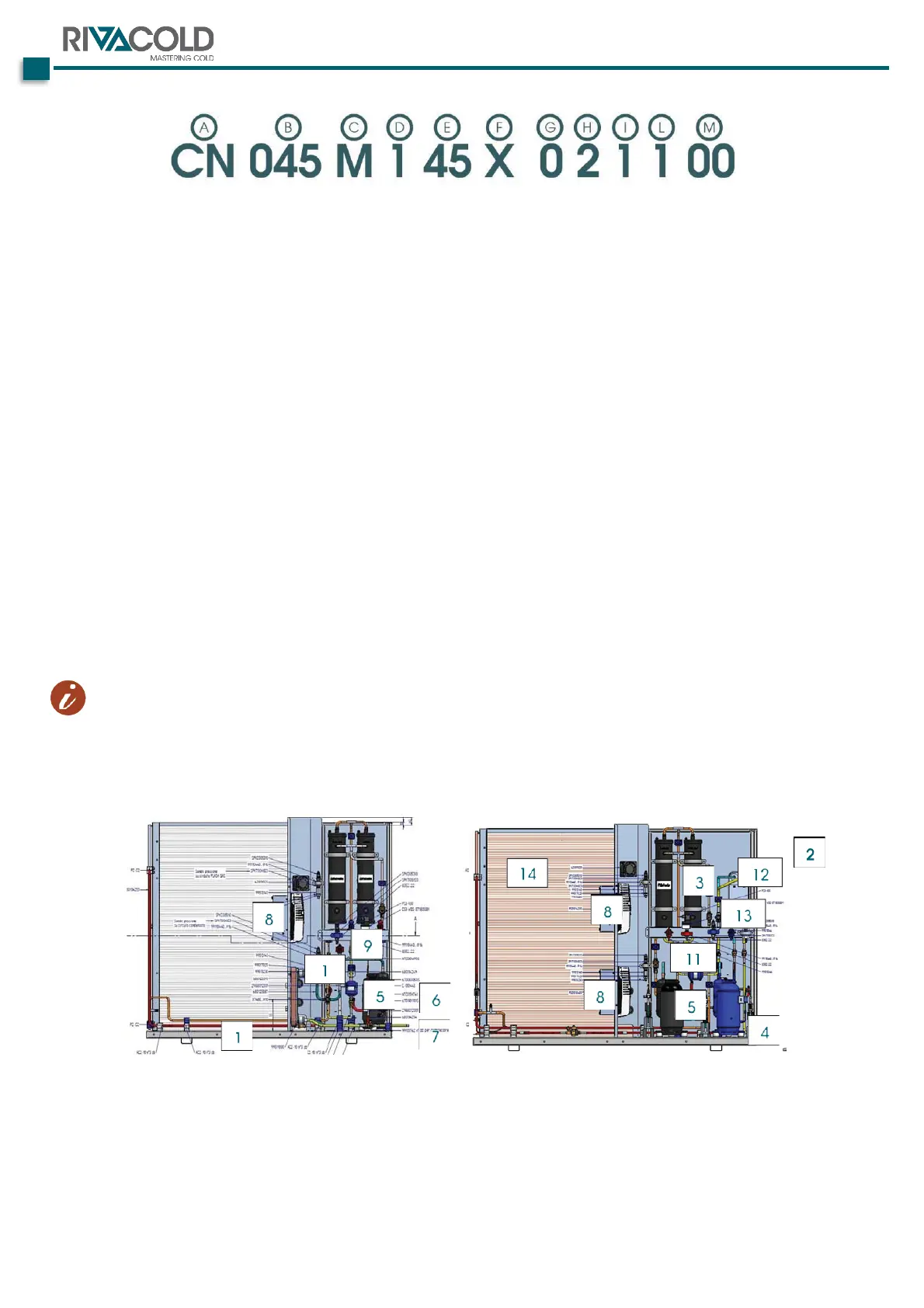
3.1.2.
Frame and components layout
The following shows the locations of the components and main connections of a type model.
1.
Frame
8.
Inverter
2.
Electrical panel
9.
Flash gas valve
3.
Received liquid tank
10.
HPV or backpressure valve
4.
Solenoid valves
11.
Liquid filter
5.
MV-LV compressors
12.
ECO Subcooler
6.
Liquid line output
13.
Liquid indicator
7.
Suction line return
14.
Gascooler

Related product manuals