RIVC000001 Pag. 15 REV. 00 11/10/10
UK
2. Restoring the factory settings
CAUTION: the following procedure will restore all factory settings for the electronic card.
We advise
that you only do this if strictly necessary and in any case, that you are assisted by a technical engineer
from Rivacold.
Cut off the power to the Blocksystem.
Press the “set” and “down” keys at the same time, then switch the Blocksystem on again while holding
down these keys.
Release the keys when the display reads “–3”.
At this point, the electronic card will re-start and its parameters will have returned to those set in the
factory. The display will read “Um” for 1 second; it will then show the temperature read by the cold
room probe.
PLEASE NOTE: THIS OPERATION RESTORES THE FACTORY SETTINGS FOR A MEDIUM-
TEMPERATURE MACHINE APPLICATION (-5/+5°C) WITH “HOT GAS” DEFROSTING.
IF YOU ARE USING AN APPLICATION OTHER THAN “MEDIUM TEMPERATURE” AND/OR A
DIFFERENT TYPE OF DEFROSTING (NOT “HOT GAS”), YOU MUST FOLLOW THE INSTRUCTIONS
IN THE FOLLOWING SECTION, AND REFER TO THE “CPP PARAMETER PROGRAMMING CHART”.
3. Rapid programming according to the application required
Level 2 programming contains a parameter known as “CPP” (to be found in the “cnf” directory) which
is used
for the rapid programming of parameters according to application and defrosting types (see
following chart).
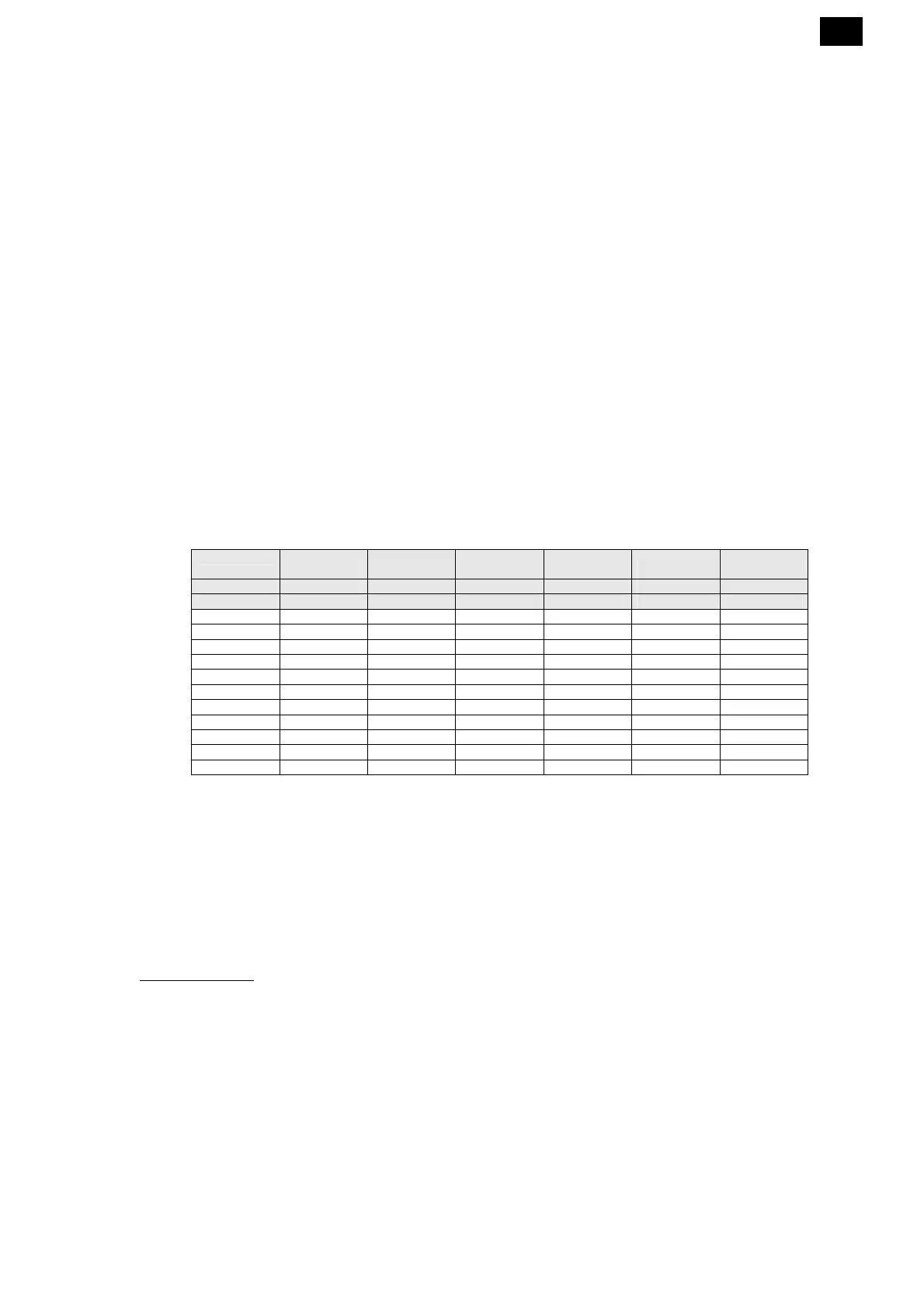
CPP parameter programming chart
Defrosting
Hot gas Hot gas Fan Heating
element
Heating
element
Application -5/+5°C -25/-15°C +2/+10°C -5/+5°C -25/-15°C
Menu Code no. CPP=1 CPP=2 CPP=3 CPP=4 CPP=5
REG SEt 2.0 -18.0 5.0 2.0 -18.0
REG diF 2.0 2.0 2.0 2.0 2.0
REG HSE 5.0 -15.0 10.0 5.0 -15.0
REG LSE -5.0 -25.0 2.0 -5.0 -25.0
DEF dtY 1 1 0 0 0
DEF dEt 15 15 15 30 30
DEF dSt 10.0 15.0 10.0 15.0 15.0
Fan FSt 8.0 -5.0 50.0 8.0 -5.0
Fan Fdt 1 2 0 1 2
Fan dt 2 2 0 2 2
Fan dFd 1 1 0 1 1
Follow the instructions in paragraph 1 to access level 2 programming
Press the “up” or “down” keys until you reach the “CnF” directory
Press the “set” key (the LOC parameter will appear)
Press the “up” key until you reach the “CPP” parameter
Press the “set” key (the number 0 will appear)
Press the “up” key until you reach the number corresponding to the required program
Then press the “set” key to confirm.
8.
ALARM SIGNALS
In the event of an alarm, the card normally activates the following:
• The relev
ant alarm code is shown on the display. In
particular, the control alternates the alarm
code and the temperature t
hat is normally shown on the display; if
there is more than one alarm,
they are displayed in succession, alternat
ed with the temperatur
e
• The alarm LED is switched on
• The alarm relay is triggered.
For so
me alarms and signals, the LED and/or relay are not triggered. The table below gives a detailed
description for each alarm and the relevant actions undertaken.
Pressing any button will deactivate the relay (if triggered) and the LED w
ill blink, while the alarm code will
remain on the display. The LED will switch off and the alarm code will disappear only when the cause
behind it has ceased. The alarm codes are listed in the table below:
 Loading...