InstructionManualIM‐293
CUSTOMER'SINFORMATIONBOX
CONTENTSAREINDEPENDENTOFRIVERHAWKDOCUMENTCONTROL
215ClintonRoad
NewHartford,NY13413
Tel:+13157684855
Fax:+13157684941
Email:info@riverhawk.com
REV
373A4058
GEDRAWINGNUMBER
RevisionF
Page9of21
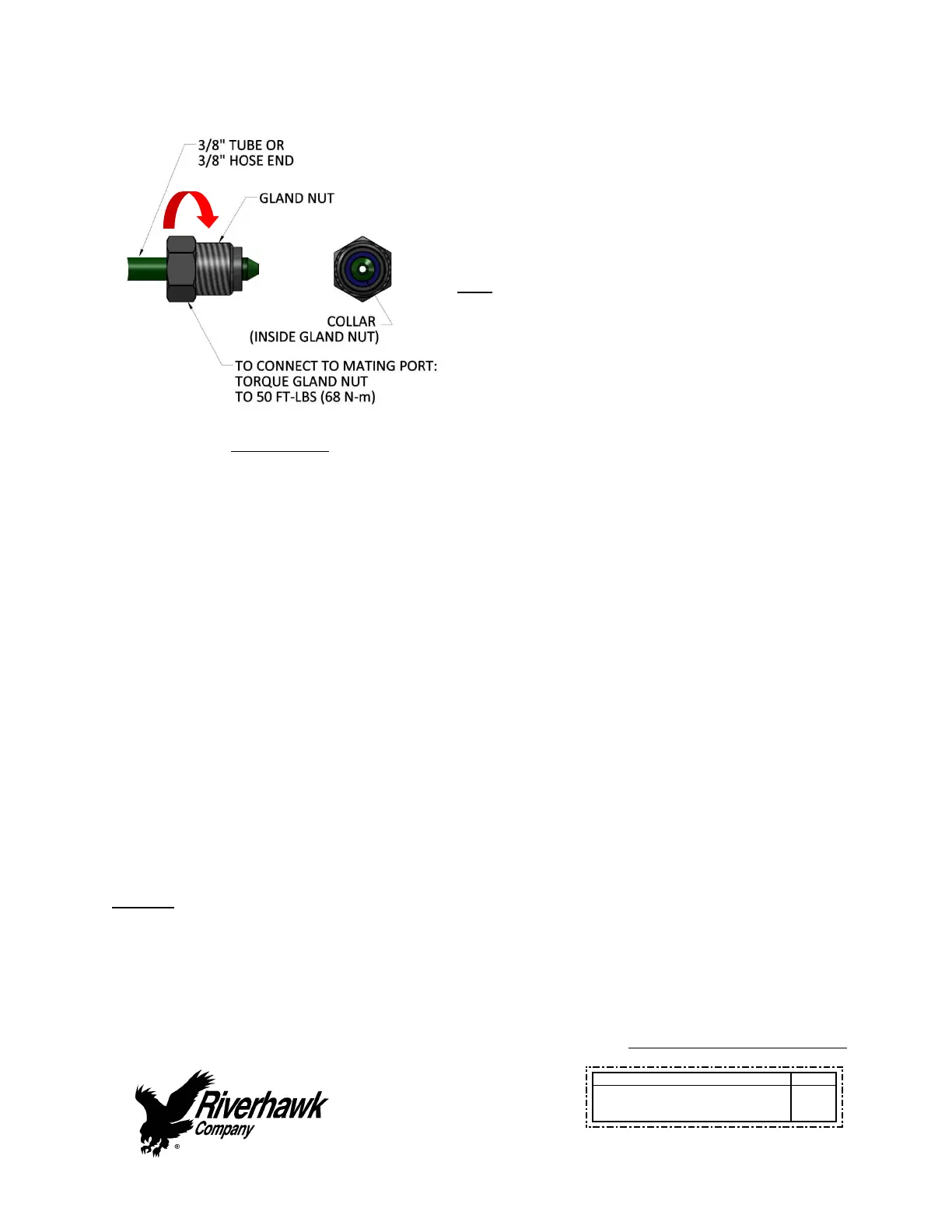
Illustration6
Slidetheglandnutdownoverthecollar.(See
Illustration6)Insertthe3/8”tubeor3/8”hose
endintotensionerorhydraulicpump.Whilefirmly
holdingthetubeorhoseendtostopitfrom
rotating,turntheglandnutclockwise(righthand
thread)andtorquetheglandnutto50FT‐LBS(68
N‐m).
Tips:
Makesureallpartsarecleanandfreefrom
debris.
Protecttheconeontheendofthe3/8”tube
or3/8”hoseendfromscratchesasthisisthe
sealingsurface.
Replaceredplasticcapswhenfinishedto
protectthethreadsandcone.
4.3CheckHydraulicPortinthePumpandTensioner
Beforeconnectingthehydraulichosetothepumportensioner,checkthehydraulicportfor
grit,dirt,andotherdebris.Cleanwithabrushand,ifnecessary,withavolatilesolventsuchas
acetone.Donotforcethedebrisdeeperintotheport.
4.4CheckHydraulicTensioner
Refertothehydraulictensionerinstructionmanualforinspectionprocedure.
5.0Operation
5.1ManualPumpOperation
Thefigures1and2attheendofthismanualdepictthelocationofthecomponentsusedto
operatethemanualpumpkits.
Step#1:Connectthepumptothetensionerwiththeappropriatehydraulichoseandopenthe
releaseknob.
WARNING
Checkthemaximumworkingpressuresofthehosesandtensionersconnectedtothepump.Do
notexceedthemaximumworkingpressureofthepump,hose,ortensioner.
 Loading...