Page 6 / 7 34-80 04/2013
2.4 ASSIGNING TEMPTRAC ADDRESS FOR MODBUS-RTU
The first step to interfacing a BAS (Building Automation Control) with a boiler or group of boilers will be the assignment of the
address number for each boiler.
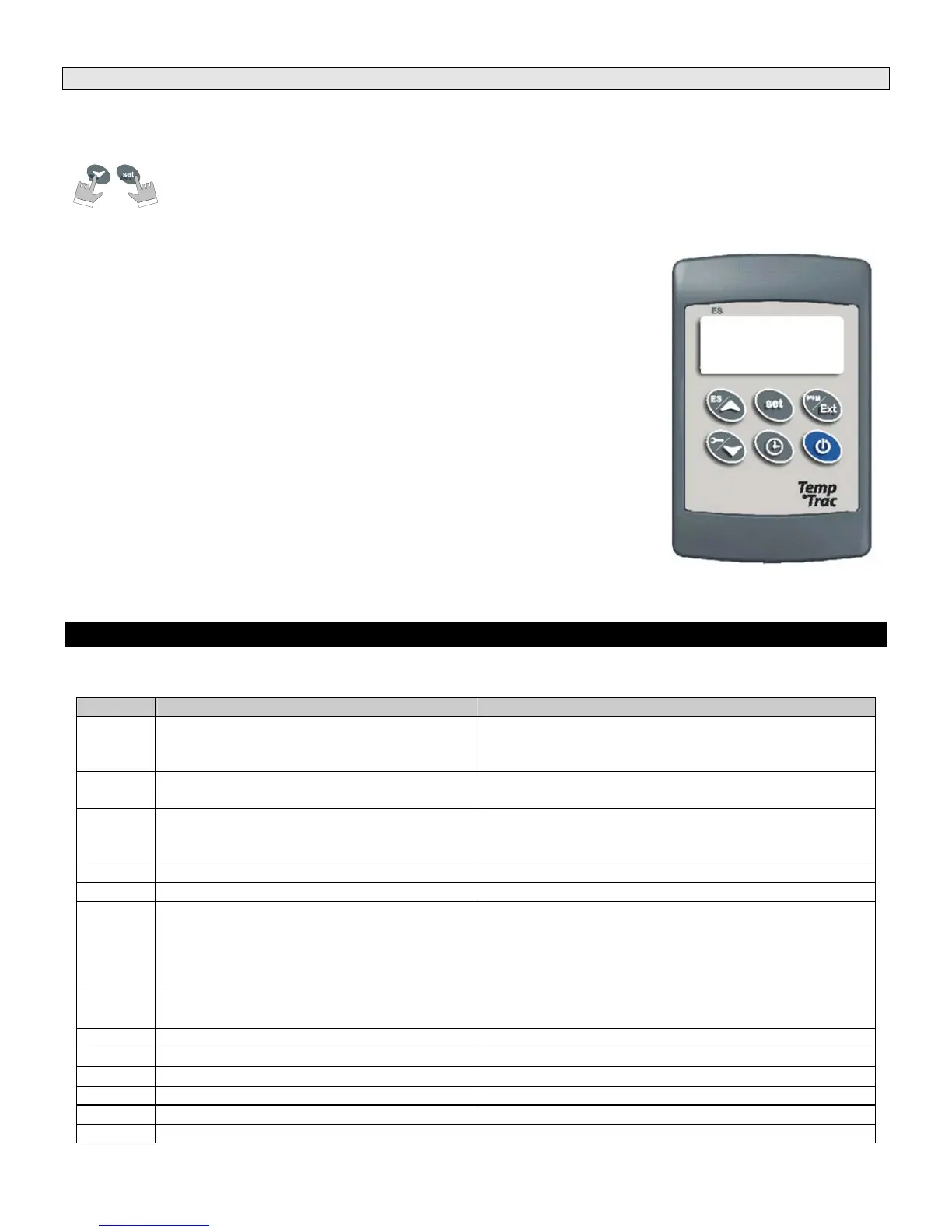
1. Enter the Programming mode by pressing the Set and DOWN key for 3s.
(lead with the SET key)
2. Press the DOWN key.
3. Select “Pr2” – “PAS” parameter and press the “SET” key.
4. The value “0 - -” with a flashing zero is displayed.
5. Use UP or DOWN keys to input the Passkey in the flashing digit; confirm the figure by
pressing “SET”. The Passkey is “321“.
6. Once you have entered the Pr2 menu press the DOWN key three times and the
parameter Adr will appear on the screen as follows:
7. Now press the SET key once and the number will begin to blink. Use the arrow key to
set the address. Each TempTrac on a RS-485 network must have a different address
8. Each boiler should be assigned a different address in order for proper communication to
occur.
Note: The default for each TempTrac is Address #1. You can assign them to any number in the range of 1-247, this is the
limitations of the MODBUS RTU standard.
3. ALARMS
Alarm messages are displayed in the upper LED readout and alternate with the default display.
An alarm LED icon is also illuminated.
Message Cause Results of alarm condition
“P1” Probe 1 failure
Call for heat and burner second stage interrupted;
modulation output % will be the PP4 parameter
(generally low fire)
“P2” Probe 2 failure
Output 3 is open
Freeze protection is disabled.
“P3” Probe 3 failure
Dynamic reset of Set1 disabled.
Outdoor reset is disabled (if used) or Flue gas
temperature protection is disabled (if used)
“HA” High-temperature limit set point exceeded Audible alarm sounds, operation continues
“LA” Low-temperature alarm Audible alarm sounds, operation continues
“AL2”
Digital Input 2 is activated for one or more of
the conditions listed in section 3.1
Unit de-energized after time delay. Audible alarm
sounds. On some products, the alarm contacts may
close for remote indication of alarm. Internal alarm
register will communicate an alarm condition through
the Modbus RTU communication link (if equipped)
“AL3”
Digital Input 3 is activated for one or more of
the conditions listed in section 3.1
Unit de-energized after time delay.
“Mn1” Maintenance alert for call-for-heat Audible alarm sounds, operation continues
“Mn2” Maintenance alert for second stage Audible alarm sounds, operation continues
“Mn3” Maintenance alert for freeze protection Audible alarm sounds, operation continues
“rtc” The real time clock has lost the setting Energy saving functions disabled
“rtF” Real time clock failure Energy saving functions disabled
“AL1” Digital Input 1 Alarm Output 1 open.
Adr
1

 Loading...