Code
Type
Range
JPt100
DA2
DA3
DA4
DA5
DA6
DA7
DA8
DA9
DB2
P01
P02
P03
P04
P05
P06
P07
P08
P09
P10
-199.9 to +400.0
o
F
-199.9 to +200.0
o
F
-199.9 to +100.0
o
F
-199.9 to +300.0
o
F
0.0 to 100.0
o
F
0.0 to 200.0
o
F
0.0 to 400.0
o
F
0.0 to 500.0
o
F
-199.9 to +900.0
o
F
-199.9 to +649.0
o
C
-199.9 to +200.0
o
C
-100.0 to +50.0
o
C
-100.0 to +100.0
o
C
-100.0 to +200.0
o
C
0.0 to 50.0
o
C
0.0 to 100.0
o
C
0.0 to 200.0
o
C
0.0 to 300.0
o
C
0.0 to 500.0
o
C
Pt100
(E) Digital input (DI) function assignment
N: None
1: SV1 to SV4 select
2: SV1 to SV2 select + RUN/STOP transfer
3: SV1 to SV2 select + AUTO/MAN transfer
4: SV1 to SV2 select + Interlock release
5: RUN/STOP transfer + AUTO/MAN transfer
6: RUN/STOP transfer + Interlock release
7: AUTO/MAN transfer + Interlock release
■ Suffix code
(1) Control Method
F: PID control with AT (Reverse action)
D: PID control with AT (Direct action)
G: Heat/Cool PID control with AT
A: Heat/Cool PID control with AT
(for Extruder [air cooling])
W: Heat/Cool PID control with AT
(for Extruder [water cooling])
(2) Measured input and Range
□□□: Refer to input range code table.
(3) Output 1 (OUT1)
[
PID control: Control output Heat/Cool PID control: Heat output]
M: Relay contact output
V: Voltage pulse output (0/12 V DC)
4: Voltage output (0 to 5 V DC)
5: Voltage output (0 to 10 V DC)
6: Voltage output (1 to 5 V DC)
7: Current output (0 to 20 mA DC)
8: Current output (4 to 20 mA DC)
T: Triac output
D: Open collector output
P: Relay contact output (Event 3 output)
R: Current output (0 to 20 mA DC)
S: Current output (4 to 20 mA DC)
X: Voltage output (0 to 5 V DC)
Transmission
Y: Voltage output (0 to 10 V DC) output
Z: Voltage output (1 to 5 V DC)
(4) Output 2 (OUT2)
[PID control: Event 3 output (Only RB100), Transmission output Heat/Cool PID control: Cool output]
N: None
(5) Power supply voltage
3: 24 V AC/DC
4: 100 to 240 V AC
(6) Digital output (DO1 to DO4)
N: None
1: 1 point (DO1)
2: 2 points (DO1, DO2)
4: 4 points (DO1 to DO4) [
Only RB400/500/700/900
]
(7) Current transformer (CT) input
N: None
P: CTL-6-P-N (1 point)
S: CTL-12-S56-10L-N (1 point)
T:
CTL-6-P-N (2 points)
U: CTL-12-S56-10L-N (2 points)
(9) Waterproof/Dustproof
N: None
1: Waterproof/Dustproof (NEMA 4X, IP66)
(10) Case color
N: White
A: Black
(11) Quick start code
N: None (No need to specify initial setting code)
1: Specify quick start code (Refer to ■Quick start code)
(8) Communication function/Digital input (DI)
N: None
5: RS-485 (RKC communication)
6: RS-485 (Modbus)
A: Digital input (2 points)
B: RS-485 (RKC communication)
+ Digital input (2 points) *
C:
RS-485 (Modbus) + Digital input (2 points) *
*
Only RB400/500/700/900
Code
Type
Range
(The digital point position is
selectable)
Programmable range
-1999 to +9999
Factory set value
:
0.0 to 100.0 (%)
301
401
501
601
701
801
0 to 1 V DC
0 to 5 V DC
0 to 10 V DC
1 to 5 V DC
0 to 20 mA DC
4 to 20 mA DC
Input range code table
S02
SA2
R02
RA2
E01
E02
EA1
EA2
B01
B02
BA1
BA2
N01
N02
NA1
NA2
A01
A02
AA1
AA2
W01
W02
WA4
D01
D02
D03
D04
D05
D06
D07
D08
D09
D10
0 to 1769
o
C
0 to 3216
o
F
0 to 1769
o
C
0 to 3216
o
F
0 to 800
o
C
0 to 1000
o
C
0 to 1600
o
F
0 to 1832
o
F
400 to 1800
o
C
0 to 1820
o
C
800 to 3200
o
F
0 to 3308
o
F
0 to 1200
o
C
0 to 1300
o
C
0 to 2300
o
F
0 to 2372
o
F
0 to 1300
o
C
0 to 1390
o
C
0 to 2400
o
F
0 to 2534
o
F
0 to 2000
o
C
0 to 2320
o
C
0 to 4208
o
F
-199.9 to +649.0
o
C
-199.9 to +200.0
o
C
-100.0 to +50.0
o
C
-100.0 to +100.0
o
C
-100.0 to +200.0
o
C
0.0 to 50.0
o
C
0.0 to 100.0
o
C
0.0 to 200.0
o
C
0.0 to 300.0
o
C
0.0 to 500.0
o
C
Code
Type
Range
Code
Type
Range
S
R
E
B
W5Re/
W26Re
Pt100
N
PLⅡ
T
K01
K02
K03
K04
K05
K06
K41
K43
K09
K10
KA1
KA2
KC7
KC8
J01
J02
J03
J04
J05
J06
J15
J07
JA1
JA2
JB9
JC8
T02
T03
T05
T06
TC7
TC8
TC9
0 to 200
o
C
0 to 400
o
C
0 to 600
o
C
0 to 800
o
C
0 to 1000
o
C
0 to 1200
o
C
-200 to +1372
o
C
-199.9 to +400.0
o
C
0.0 to 400.0
o
C
0.0 to 800.0
o
C
0 to 800
o
F
0 to 1600
o
F
-328 to +2501
o
F
-100.0 to +752.0
o
F
0 to 200
o
C
0 to 400
o
C
0 to 600
o
C
0 to 800
o
C
0 to 1000
o
C
0 to 1200
o
C
-200 to +1200
o
C
-199.9 to +300.0
o
C
0 to 800
o
F
0 to 1600
o
F
-328 to +2192
o
F
-199.9 to +550.0
o
F
-199.9 to +100.0
o
C
-100.0 to +200.0
o
C
-199.9 to +300.0
o
C
0.0 to 400.0
o
C
0.0 to 600.0
o
F
-199.9 to +300.0
o
F
-328 to +752
o
F
K
J
■ Quick start code (Initial setting code)
□□□□-□
(A) (B) (C) (D) (E)
(A) DO1 (Event function 1) (C) DO3 (Event function 3)
1
(B) DO2 (Event function 2) (D) DO4 (Event function 4)
2
N:
A:
B:
C:
D:
E:
F:
G:
H:
J:
K:
L:
Q:
R:
T:
U:
V:
W:
X:
Y:
Z:
1:
2:
3:
4:
5:
None
Deviation high
Deviation low
Deviation high/low
Band
Deviation high with hold action
Deviation low with hold action
Deviation high/low with hold action
Process high
Process low
Process high with hold action
Process low with hold action
Deviation high with re-hold action
Deviation low with re-hold action
Deviation high/low with re-hold action
Band (High/Low individual setting)
SV high
SV low
Deviation high/low (High/Low individual setting)
Deviation high/low with hold action (High/Low individual setting)
Deviation high/low with re-hold action (High/Low individual setting)
Heater break alarm (HBA)
Control loop break alarm (LBA)
FAIL
Monitor during RUN
Output of the communication monitoring result
4. MODEL CODE
1
In case of RB100, this code is selectable when "P" is specified for "(4) output 2 (OUT2)."
2
In case of RB100, this code must be "N: None."
(12) Instrument specification
/Y: Version symbol
M: Relay contact output
V:
Voltage pulse output (0/12 V DC)
4: Voltage output (0 to 5 V DC)
5: Voltage output (0 to 10 V DC)
6: Voltage output (1 to 5 V DC) Cool output
7: Current output (0 to 20 mA DC)
8: Current output (4 to 20 mA DC)
T: Triac output
D: Open collector output
□□□□-□□-□*□□-□□/□□/Y
(1) (2) (3) (4) (5) (6) (7 ) (8) (9) (10) (11) (12)
RB100
RB400
RB500
RB700
RB900
Modbus is a registered trademark of Schneider Electric.
Company names and product names used in this manual are the trademarks or registered trademarks of the respective companies.
HEADQUARTERS:
16-6, KUGAHARA 5-CHOME, OHTA-KU TOKYO 146-8515 JAPAN
PHONE: 03-3751-9799 (+81 3751 9799) E-mail: info@rkcinst.co.jp
FAX: 03-3751-8585 (+81 3751 8585)
OCT. 2016
The first edition: AUG. 2009 [IMQ00]
The fourth edition:
OCT. 2016 [IMQ00]
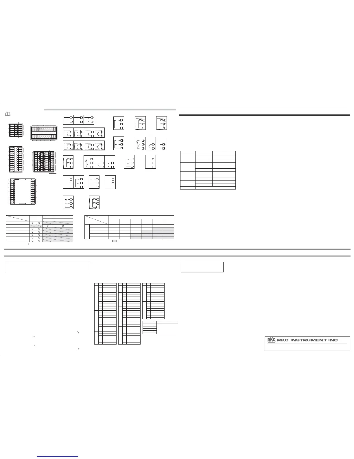
2.2 Terminal Configuration
To prevent malfunctioning,
do not connect wires to unused terminals.
25
26
27
RS-485
SG
T/R (A)
T/R (B)
(17)
Communication
(Optional)
13
14
15
RS-485
SG
T/R (A)
T/R (B)
(8)
Communication
(Optional)
Relay contact (2)
DO4
NO
NO
DO3
COM
7
8
9
(12)
Digital output
1
(DO3, DO4)
(Optional)
Relay contact (2)
DO4
NO
NO
DO3
COM
19
20
21
(10)
Digital output
1
(DO3, DO4)
(Optional)
Dry contact input
DI2
DI1
COM
(
-
)
22
23
24
(16)
Digital input
2
(DI1, DI2)
(Optional)
Dry contact input
DI2
DI1
COM
(
-
)
16
17
18
(9)
Digital input
2
(DI1, DI2)
(Optional)
CT input
(7)
CT input
(CT1, CT2)
(Optional)
CT2
CT1
COM
16
17
18
(14)
CT input
(CT1, CT2)
CT input
(Optional)
CT2
CT1
COM
13
14
15
(11)
CT input
(CT1, CT2)
CT input
(Optional)
CT2
CT1
COM
22
23
24
Output 2 (OUT2):
・PID control: OUT2 can be used as the transmission output
(Specify when ordering)
・Heat/Cool PID control:
OUT2 corresponds to the cool-side output
・Specify when Event 3 output (Only RB100)
Digital output (DO1 to DO4 [RB100: DO1, DO2]):
・Output of the Event function can be allocated to DO1 to DO4.
Output assignment
Output 1 (OUT1):
・PID control: OUT1 is dedicated to control output
・Heat/Cool PID control:
OUT1 can be used only as the heat-side output
1
Digital input assignment
The following functions can be assigned as digital input.
(Specify when ordering)
2
SV selection, Auto(AUTO)/Manual(MAN) transfer,
RUN/STOP transfer, Interlock release
1
2
100-240V
AC
L
N
1
2
24V
AC
L
N
1
2
24V
DC
+
-
(1)
Power supply
16
17
18
RTD
A
B
B
RTD
17
18
Thermocouple
TC
+
-
17
18
Voltage/Current
IN
+
-
(15)
Measured input
10
11
12
RTD
A
B
B
RTD
11
12
Thermocouple
TC
+
-
11
12
Voltage/Current
IN
+
-
(5)
Measured input
Relay contact (2)
10
11
12
DO2
NO
NO
DO1
COM
(13)
Digital output
1
(DO1, DO2)
(Optional)
Relay contact (2)
7
8
9
DO2
NO
NO
DO1
COM
(4)
Digital output
1
(DO1, DO2)
(Optional)
13
14
15
RS-485
SG
T/R (A)
T/R (B)
(6)
Communication and
Digital input (DI1, DI2)
2
(Optional)
Dry contact input
DI2
DI1
COM
(
-
)
13
14
15
3
4
NO
Relay contact (1)
OUT2
3
4
Voltage pulse/
Voltage/Current
OUT2
+
-
3
4
Triac
Triac
OUT2
3
4
Open collector
OUT2
(2)
Output 2
1
5
6
NO
Relay contact (1)
OUT1
5
6
Voltage pulse/
Voltage/Current
OUT1
+
-
5
6
Triac
Triac
OUT1
5
6
Open collector
OUT1
(3)
Output 1
1
3. SPECIFICATIONS
Communication [Optional]
Based on RS-485 EIA standard Interface:
RKC communication
(Based on ANSI X3.28-1976 subcategory 2.5, A4)
Protocol:
Modbus-RTU
Loader communication
Based on ANSI X3.28-1976 subcategory 2.5, A4Protocol:
Connection with a loader communication cable
for our USB converter COM-K (sold separately).
Connection method:
Start/Stop synchronous typeSynchronous method:
Start bit: 1
Data bit: 8
Parity bit: Without
Stop bit: 1
・Data bit configuration is fixed to the above value.
・Address is fixed at 0.
Data bit configuration:
9600 bpsCommunication speed:
One controller (Only COM-K)Maximum connections:
250 ms
Sampling cycle:
Approx. 200
μA
(Only RTD)
Sensor current:
First order lag digital filter: 0 to 100 seconds (0: filter OFF)
Action at input short circuit:
Downscale (RTD)
Upscale or downscale (TC)
Action at input break:
Upscale (RTD)
Downscale or Indicates the value near 0
(Voltage/Current input)
Control
Autotuning, Startup tuning, Fine tuningAdditional function:
PID control (Reverse/Direct action)
Heat/Cool PID control
P, PI, PD, or ON/OFF action is available
Control type:
Standard
cUL: CAN/CSA-C22.2 No.61010-1
Safety standards: UL: UL61010-1
OVERVOLTAGE II, POLLUTION DEGREE 2,
Class II (Reinforced insulation)
CE marking: LVD: EN61010-1
EMC: EN61326-1
RCM: EN55011
Panel sealing: NEMA 4X (NEMA250) IP66 (IEC60529)
[Front panel (if specified in the model code)]
Measured input
1 point
Number of input:
TC input: K, J, T, S, R, E, B, N (JIS C1602-1995),
PLII (NBS), W5Re/W26Re (ASTM-E988-96)
Input impedance: 1 MΩ or more
Influence of external resistance: Approx. 0.25μV/Ω
RTD input: Pt100 (JIS C1604-1997),
JPt100 (JIS C1604-1997, JIS C1604-1981 of Pt100)
Influence of input lead: Approx. 0.02 %/Ω of span
(10 Ω or less per wire)
Voltage input: 0 to 1 V DC, 0 to 5 V DC, 1 to 5 V DC, 0 to 10 V DC
Input impedance: Approx. 1 MΩ or more
Current input:
0 to 20 mA DC, 4 to 20 mA DC
Input impedance: Approx. 250Ω
(Connect a 250Ω resister to the input terminals)
Current transformer (CT) input [Optional]
CTL-6-P-N: 0.0 to 30.0 A
CTL-12-S56-10L-N: 0.0 to 100.0 A
Input range:
1 second
Sampling cycle:
2 pointsNumber of inputs:
Digital input (DI) [Optional]
Capture judgment time: Approx. 250 ms
2 points (DI1, DI2) Isolated inputNumber of inputs:
Open state: 500 kΩ or more
Dry contact input:
Close state: 10 Ω or less
Contact current: 3.3 mA or less
Voltage at open: Approx. 5 V DC
Triac output:
Output method: AC output (Zero-cross method)
Allowable load current: 0.5 A (Ambient temperature 40
o
C or less)
Ambient temperature 50
o
C: 0.3 A
ON voltage: 1.6 V or less (at maximum load current)
Load voltage: 75 to 250 V AC
Minimum load current: 30 mA
Output
6 points (RB100: 4 points)Number of outputs:
Mechanical life: 20 million times or more
(Switching: 360 times/min [no-load])
Relay contact output (1):
Contact type: 1a contact
Contact rating (Resistive load): 250 V AC 3 A, 30 V DC 1 A
Electrical life: 100,000 times or more (Rated load)
Mechanical life: 20 million times or more
(Switching: 360 times/min [no-load])
Relay contact output (2):
Contact type: 1a contact
Contact rating (Resistive load): 250 V AC 1 A, 30 V DC 0.5 A
Electrical life: 150,000 times or more (Rated load)
Output impedance: 1 MΩ or more
Current output:
Output current (Rating): 0 to 20 mA DC, 4 to 20 mA DC
Allowable load resistance: 500 Ω or less
Voltage pulse output:
Output voltage (Rating): 0/12 V DC
ON voltage: 10 V to 13 V (at 20 mA)
Allowable load resistance: 600 Ω or more (20 mA or less)
Not using OUT2: 40 mA or less
OFF voltage: 0.5 V or less
Output impedance: 0.1 Ω or less
Voltage output:
Output voltage (Rating): 0 to 5 V DC, 1 to 5 V DC, 0 to 10 V DC
Allowable load resistance: 1 kΩ or more
PV bias: -1999 to +9999
o
C or
-199.9 to +999.9
o
C (TC/RTD)
-Input span to + Input span (
Voltage/Current input
)
Input accuracy:
*1: Accuracy is not guaranteed for less than
-100
o
C
*2: Accuracy is not guaranteed for less than 400
o
C for Input type R, S, B, and
W5Re/W26Re.
Leakage current at OFF: 0.1 mA or less
ON voltage: 2 V or less (at maximum load current)
Open collector output:
Output method: Sink type
Allowable load current: 100 mA
Load voltage: 30 V DC or less
Minimum load current: 0.5 mA
Input type Input range Accuracy
K, J, T, E
N, R, S, PLII,
W5Re/W26Re
B
±(0.2 % of span + 1 digit)
Voltage/Current input
Pt100, JPt100
Less than -100
o
C
-100
o
C or more,
Less than +500
o
C
+500
o
C or more
±(2.0
o
C + 1 digit)
±(1.0
o
C + 1 digit)
±(0.2 % of Reading + 1 digit)
Less than 0
o
C
0
o
C or more,
Less than 1000
o
C
1000
o
C or more
±(4
o
C + 1 digit)
±(2
o
C + 1 digit)
±(0.2 % of Reading + 1 digit)
Less than 400
o
C
400
o
C or more,
Less than 1000
o
C
1000
o
C or more
±(70
o
C + 1 digit)
±(2
o
C + 1 digit)
±(0.2 % of Reading + 1 digit)
Less than 200
o
C
200
o
C or more
±(0.4
o
C + 1 digit)
±(0.2 % of Reading + 1 digit)
*1
*2
*2
Absolute humidity:
MAX.W.C 29.3 g/m
3
dry air at 101.3 kPa
Allowable ambient humidity:
10 to 90 %RH
Allowable ambient temperature: 0 to 50
o
C
Installation environment conditions: Indoor use
Altitude up to 2000 m
Memory backup:
Number of writing: Approx. 1,000,000 times
Backed up by non-volatile memory
Data storage period: Approx. 10 years
Power consumption (at maximum load):
RB900:
6.0 VA (at 24 V AC)
147 mA (at 24 V DC)
6.2 VA (at 100 V AC)
9.0 VA (at 240 V AC)
RB700:
5.8 VA (at 24 V AC)
147 mA (at 24 V DC)
6.0 VA (at 100 V AC)
8.7 VA (at 240 V AC)
RB100:
4.7 VA (at 24 V AC)
108 mA (at 24 V DC)
5.5 VA (at 100 V AC)
8.5 VA (at 240 V AC)
RB400/500:
5.8 VA (at 24 V AC)
141 mA (at 24 V DC)
6.0 VA (at 100 V AC)
8.7 VA (at 240 V AC)
General specifications
Power supply voltage: 90 to 264 V AC
[Including power supply voltage variation]
(Rating 100 to 240 V AC), 50/60 Hz
21.6 to 26.4 V AC
[Including power supply voltage variation]
(Rating 24 V AC)
21.6 to 26.4 V DC
[Including power supply voltage variation]
(Rating 24 V DC)
Weight: RB700: Approx. 200 g
RB900: Approx. 250 g
RB100: Approx. 120 g
RB400: Approx. 185 g
RB500: Approx. 190 g
Panel sheet: Polyester
Material:
Terminal block: PPE *
Front panel, Case:
PC *
Rush current: 5.6 A or less (at 100 V AC)
13.3 A or less (at 240 V AC)
16.3 A or less (at 24 V AC)
11.5 A or less (at 24 V DC)
* Flame retardancy: UL94V-1
NO: Normally open
13
14
15
16
17
18
19
20
21
22
23
24
1
2
3
4
5
6
7
8
9
10
11
12
(RB900)
(8)
(10)
(9)
(11)
(1)
(4)
(5)
(2)
(3)
13
14
15
16
17
18
19
20
21
22
23
24
1
2
3
4
5
6
7
8
9
10
11
12
(RB400)
(8)
(10)
(9)
(11)
(1)
(4)
(5)
(2)
(3)
(7)
(6)
713
6
5
4
3
2
1
11
10
9
8
12
17
16
15
14
18
(RB100)
(1)
(2)
(3)
(4)
(5)
(RB500)
(1) (2) (3) (4) (5)
(8) (9) (10) (11)
13 14 15 16 17 18 19 20 21 22 23 24
123456789101112
13
14
15
16
17
18
19
20
21
22
23
25
27
26
24
1
2
3
4
5
6
7
8
9
10
11
12
(RB700)
(1)
(2)
(3)
(12)
(17)
(13)
(14)
(15)
(16)
Maximum number of digital outputs (DO) by combinations of output (OUT1 and OUT2) of RB400/500/700/900:
M, T, D 4
4
4
4
4
2
4
4
4
2
4
2
4
2
2
2
4
2
2
2
4
4
422 224
4
4
Current
output
Voltage
output
V
(20 mA)
V
(10 mA)
M, T, D
OUT2 (Including transmission output)
No OUT2
output
OUT1*
Current output
Voltage output
V (Load: 10 mA)
V (Load: 20 mA)
( : It represents selection of digital outputs DO3 and DO4 is not available.)
* When the instrument has two digital outputs (DO1 and DO2) and no OUT2 output, "V" type output (load: 40 mA)
can be specified for OUT1.
Output type:
( [ ] : Model code symbol, : Indicates that an output specification is supported.)
Relay contact output (1)
[M]
[D]
[T]
[V]
[M]
Relay contact output (2)
Voltage pulse output
Current output
Voltage output
Triac output
Open collector output
OUT2
RB400/500/700/900RB100
DO1 to DO4DO1, DO2
OUT1

 Loading...


