EasyManua.ls Logo

RKI Instruments Beacon 200 User Manual

Default Icon
56 pages
To Next Page IconTo Next Page
Page #1 background imageLoading...
Page #1 background image
www.rkiinstruments.com
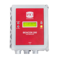
Beacon 200 Gas Monitor
Operators Manual
Part Number: 71-0059RK
Revision: F
Released: 3/31/16

Questions and Answers:

RKI Instruments Beacon 200 Specifications

General IconGeneral
Inputs4-20 mA
Power24 VDC
EnclosureNEMA 4X, IP66
Gas TypesCombustible, Oxygen, Toxic
Detection GasesLEL, O2, H2S, CO
DisplayLCD
Operating Temperature-4° to 122°F (-20° to 50°C)
AlarmsAudible and visual alarms
CertificationsATEX, IECEx
TypeFixed Point Gas Detector
RangeO2: 0-30% vol, H2S: 0-100 ppm, CO: 0-500 ppm, LEL: 0-100% LEL
ResolutionO2: 0.1% vol, H2S: 1 ppm, CO: 1 ppm, LEL: 1% LEL
Humidity Range0-99% RH (non-condensing)

Summary

Chapter 1 Introduction

Beacon 200 Specifications

Chapter 3 Installation and Start Up

Mounting the Beacon 200 Gas Monitor

Provides step-by-step instructions for physically installing the monitor at a mounting site.

Starting Up the Beacon 200 Gas Monitor

Details the procedure to place the Beacon 200 into normal operation after installation.

Wiring the Beacon 200 Gas Monitor

Connecting the AC Power Source

Details the procedure for connecting the AC power source, including wire selection and circuit breaker requirements.

Connecting the DC Power Source

Explains how to connect a DC power source, including AC/DC priority and battery backup considerations.

Connecting RKI Detector Heads

Guides the connection of RKI detector heads, specifying wire types and terminal usage.

Chapter 4 Operation

Visual and Audible Alarm Indications

Lists visual and audible indications for Alarm 1, Alarm 2, Fail, and Low Battery conditions.

Alarm 1 Condition Details

Details the indications for Alarm 1 and provides steps for responding to it.

Alarm 2 Condition Details

Details the indications for Alarm 2 and provides steps for responding to it.

Fail Condition Details

Details the indications for a fail condition and suggests steps for responding to it.

Chapter 5 Channel Control and Setup

Configure Channel Settings Menu

Guides users through changing channel parameters like alarm levels, delays, and relay actions.

Chapter 6 Input Setup Program

Setting Up Channels and Detector Heads

Provides steps to configure detector head types, units, gas types, and full scale settings for channels.

Chapter 7 Maintenance

Calibration Program Procedures

Details the process for calibrating active channels using direct connect or 4-20 mA transmitter detector heads.

Calibrating 4-20 mA Detector Heads

Guides the calibration process for 4-20 mA transmitter detector heads.

Troubleshooting Guide

Troubleshooting Common Issues

Describes symptoms, causes, and recommended actions for common problems like no power or false alarms.

Related product manuals