The multimeter (9 pic.1) indicates also the grid current,
it depends on the set-up of the output circuit and the
input power. The grid current does not have to exceed
90 mA. A protection circuits makes the linear usage
impossible when this value is exceeded and indicates
this condition switching ON the danger indicator A (16
pic. 1) and preventing the linear operation, to restart
the KLV 2000 operation bring the command Lin/ON on
OFF (12 pic. 1). Additional reason for the protection to
be entered - therefore the lightening of the
corresponding light and the KLV 2000 stoppage is
the non proper operation of the cooling fan. An
electronic control on the fan motor shows an eventual
anomaly on the protection circuit in this condition the
restarting of KLV 2000 operation by means of the Lin/
ON command is not working, and a technician has to
be contacted. The protection is entered also when the
linear is switched ON, if the command Lin/ON is on
position ON (12 pic. 1), because the fan speed required
few seconds to reach the fixed level, in this case the
operation on command Lin/ON make the KLV 2000
restart.
The Delay/ON command (11 pic. 1) enters, in position
ON, a delay of about 2 seconds when releasing the
relay of commuting, necessary in SSB an CW in the
case when one of the back plug PTT (5 or 6 pic. 2) is
not used so that KLV 2000 commutes by the inner VOX
circuit. The delay is for avoiding the antenna relay to
standby when the input signal is zero during the short
transmission break.
The antenna preamplifier is inserted by means of the
command Pre/ON (13 pic. 1). To use, adjust the pre-
tune command (5 pic. 1) to the used frequency. When
the amplifier is off, syntonize a signal close to the
working frequency in the receiver, switch the
preamplifier ON and slowly turn the command Pre Tune
in a direction or the other to find the max deflection
position of the s-meter of the receiver.
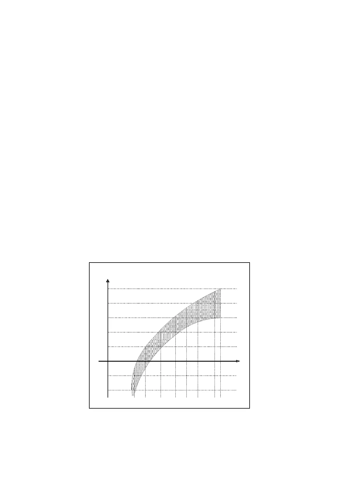
The preamplifier works as a Pass-band circuit, with a
limited width. Across tuning frequency (16 pic. 1) amplify
the signal 30 to 9,5 MHz and lower it down 9,5 to 6,5
MHz as per the diagram in pic. 9, this way it enables,
also thank to the limited passing-band, to decrease the
intermodulation of loud signals on adjacent frequencies
and to amplify the low signals in high bands.
dB
Band
0
-10
+10
+15
+20
+25
-5
+5
10m12m15m17m20m30m40m
Fig 9
Gain versus frequency preamplifier curve chart
G
- 14 -