- 5 -
1) Netz
Netzkabel
2) GND
Erdungsanschluß
3) Ventilator
Belüftungsgitter (immer freihalten, niemals blockieren)
4) ALC
Diese RCA-Buchse wird für den
Transceiveranschluß der ALC-Regelung benutzt
5) PTT+
Eine Plusspannung über 6V schaltet das Senden der
Linear ein
6) PTT-
Ist dieser Eingang geerdet, aber mit einer Spannung
unter 4 V, geht die Linear auf Sendung
7) RTX
HF-Eingangsbuchse PL-Norm für den ansteuernden
Transceiver.
8) ANT
Anschlussbuchse für Antenne (PL-Norm) /
Ausgangsbuchse für HF-Leistung
9) Anschlüsse und Notizen (Ratschläge)
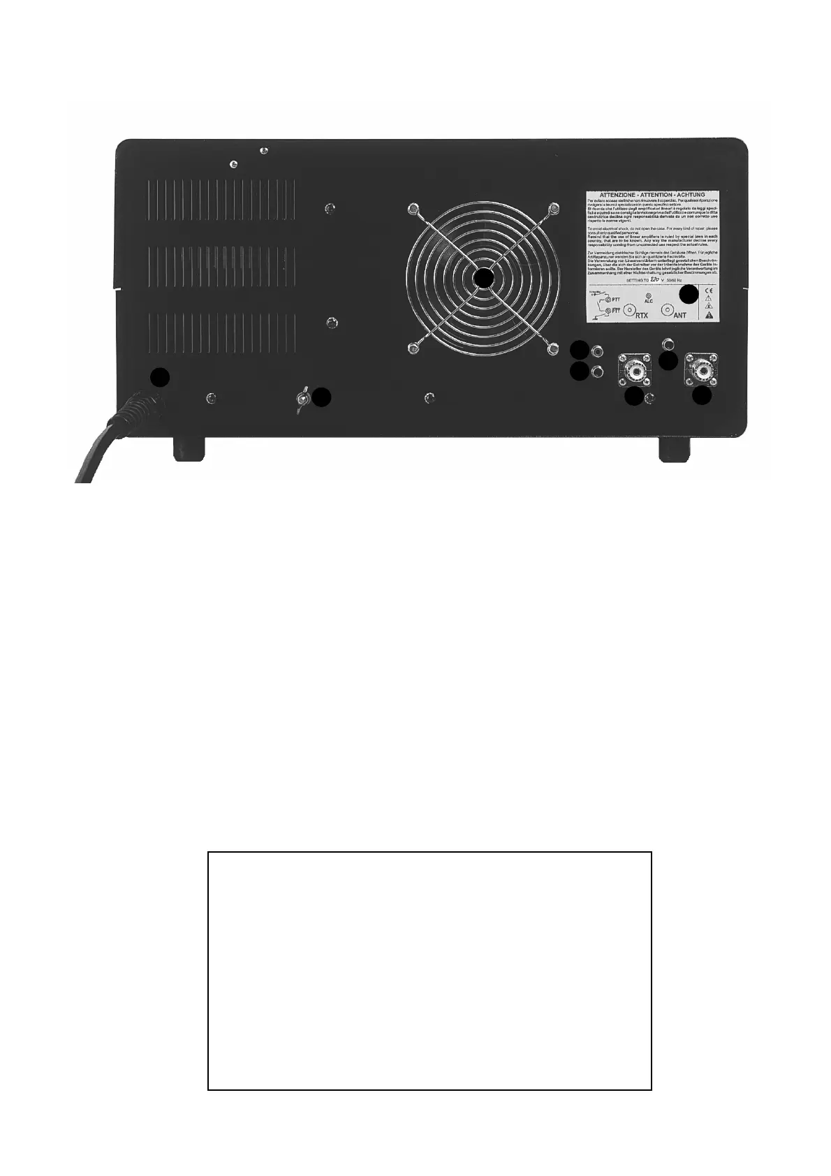
Rückwand - Rear description
1) Network
Supply cable input
2) GND
Connect the amplifier to the station ground bus at
this point
3) Fan
Fan grid (always keep it free of any materials that
could obstruct it)
4) ALC
This RCA jack is used for connection to the trasceiver
ALC control input
5) PTT+
A positive tension exceding 6V cause the commute
to linear transmission
6) PTT-
When this input in grounded, however with a tension
lower than 4 V, it causes commute to linear
transmission
7) RTX
The RF input from the transceiver should be
connected to this SO 239 connector
8) ANT
This SO 239 connector provides the RF output to the
antenna
9) Connections and notices (advices)
Vorsicht !!
Betreiben Sie diesen Verstärker nie ohne guten
Erdungsanschluß oder eine angeschloßene Antenne
oder Dummy Load an der Buchse ANT (8).
CAUTION
Never operate this equipment without connecting it to a
good earth ground. Likewise, never operate the amplifier
wthout having an antenna or dummy load connected to
the rear panel ANT jack (8)
Abb. 2
1
2
3
4
5
6
7
8
9