38
User's Guide Fireface UC © RME
21. Stand-alone Operation
The Fireface UC has an internal memory to permanently store all configuration data. The data
is stored directly after any change, and are loaded at power-on. Saved settings are:
Settings dialog
Sample rate, clock mode Master/Slave, configuration of the channels and the digital I/Os.
TotalMix
The complete mixer state.
This also improves the clock situation immediately after power-on, avoiding wrong clocking and
noise disturbances in a complex setup, caused by wrong synchronization. Usually the unit will
be configured by the Windows or Mac driver, so for the time between power-on of the computer
up to the loading of the driver its state might be wrong.
This total configuration feature in stand-alone operation - without any connected computer -
turns the Fireface into lots of dedicated devices, see examples in chapter 24. Furthermore To-
talMix (and with this all application examples) can be MIDI controlled even in stand-alone op-
eration, see chapter 32.7, Stand-Alone MIDI Control.
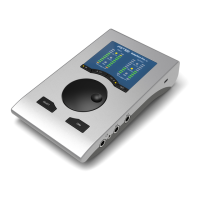
21.1 Front Panel Operation
The knob on the front, a so called rotary encoder, serves to set the input gains and output vol-
umes directly at the unit. The encoder operates either in CHANNEL or in LEVEL mode. Pushing
the knob changes between these modes. The currently active mode is indicated by a green
LED.
In CHANNEL mode, selection of the desired channel is done by turning
the knob. The following strings will be shown in the display:
i.1 bis i.4 Mic input 1 up to instrument/line input 4
L.1 bis L.6 Line output 1 up to line output 6
PH Phones (line output 7/8)
SP SPDIF output
A.1 bis A.8 ADAT output 1 up to 8
i.1 / i.2
The gain of the two microphone inputs 1/2 can be defined in the range of 10 dB up to 65 dB in
steps of 1 dB. Additionally the setting 0 dB is available. The gain change is performed in analog
domain in hardware.
i.3 / i.4
The gain of the two instrument/line inputs 3/4 can be defined in the range of 0 dB up to 18 dB in
steps of 0.5 dB. The x.5 dB values are signalled by a dot to the right. The gain change is per-
formed in analog domain in hardware.
L.1 bis L.6, PH, SP, A.1 bis A.8
The output levels of these outputs can be defined in the range +6 dB down to –58 dB in steps of
1 dB. Additionally the setting maximum attenuation (Mute) is available. The gain change is per-
formed digitally by TotalMix.
Stereo Mode
Pushing the knob for more than a second activates the Link (Gang) mode. The display will show
off or on. In stereo (on) mode, the display only presents the left channels of a stereo pair (L1,
L3, L5...). The gain and volume setting is then valid for both channels.
 Loading...