7. The ADC Module
The ADC Module replaces the analog D-sub output by a high quality digital converter card. The
card includes clock generation, clock recovery (SteadyClock) and AD-conversion.
7.1 DIP Switches
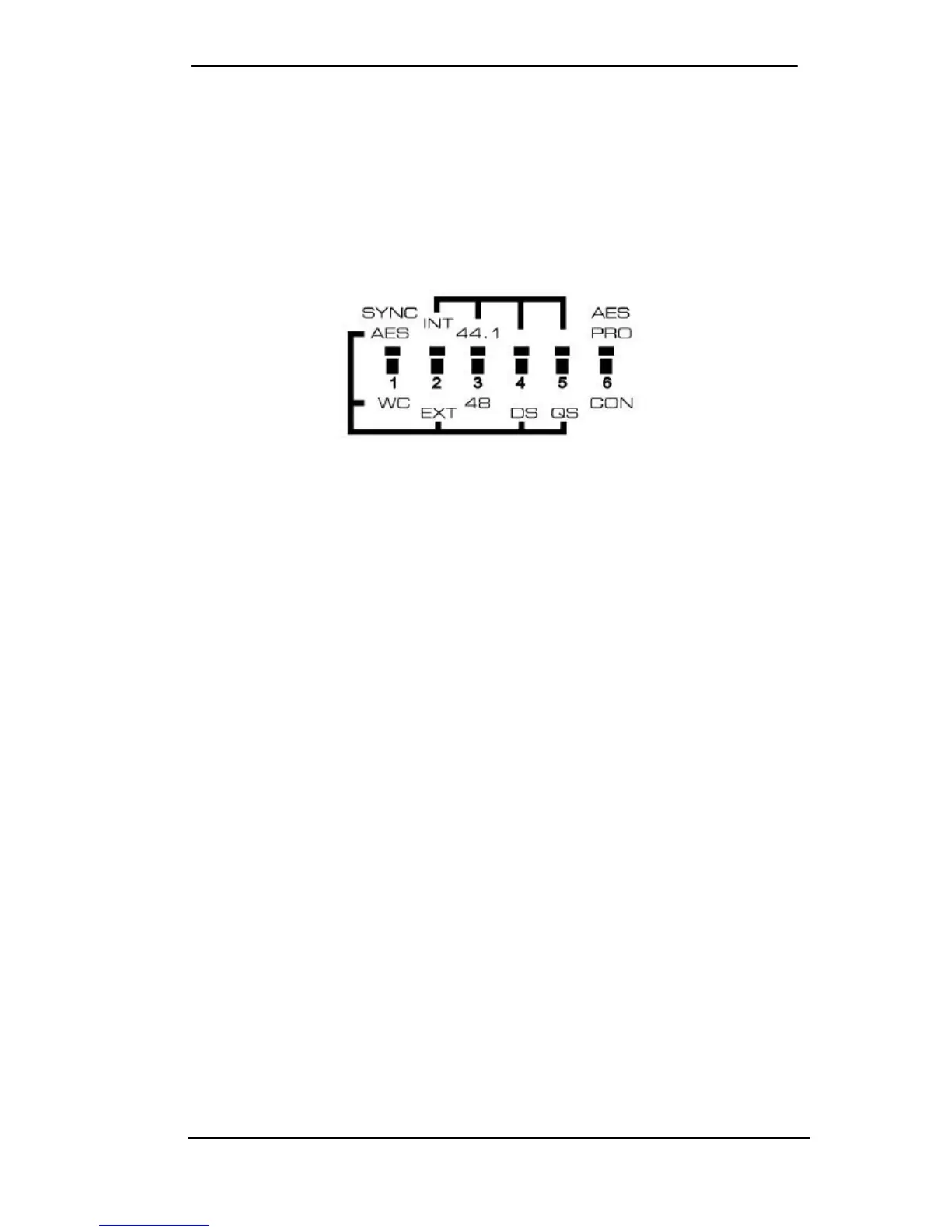
The DIP switches are used to configure the ADC Module. The following diagram, also printed
on the back of the unit, shows the function controlled by each switch.
DIP Switch Function
1 External synchronization source AES (D-sub) or word clock (BNC)
2 Clock internal (Master) or external (Slave)
3 Internal Clock 44.1 kHz or 48 kHz
4 Activates Double Speed Mode*
5 Activates Quad Speed Mode*
6 AES output signal Professional or Consumer
*Note on DIP switch 4/5:
At internal clock, the switches DS and QS multiply the value set with switch 3 by a factor of 2 or
4. So if switch 3 is set to 48 kHz, switch 4 will turn it into 96 kHz, switch 5 turns it into 192 kHz.
At external clock switch 3 is of no meaning, because the unit is synchronized to the incoming
clock. However, switch 4 and 5 define the frequency range between Single Speed, Double
Speed and Quad Speed. For example if the OctaMic shall operate at 176.4 or 192 kHz, switch
5 has to be set to the lower position. The OctaMic will now generate an output signal in the
Quad speed range (176.4 or 192 kHz), even with a word clock input signal of only 44.1 kHz, or
an AES input signal signal of 96 kHz.
 Loading...