This document is a service manual for the Roadstar CD-357MP/FM car stereo, a CD/MP3 player with ESP (Electronic Skip Protection) and RDS (Radio Data System) receiver. It provides detailed information for servicing the device, including a bill of materials and circuit board layouts.
Function Description:
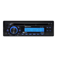
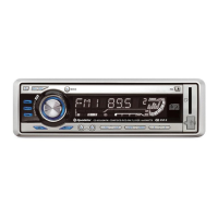
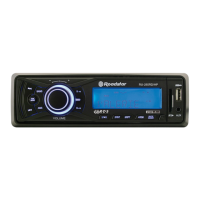
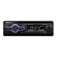
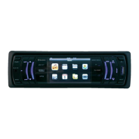
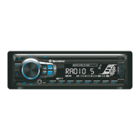
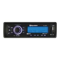
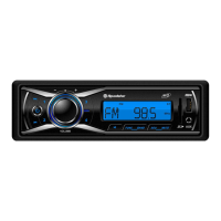
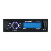
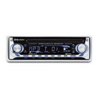
The Roadstar CD-357MP/FM is designed to provide in-car audio entertainment, supporting both traditional CD playback and modern MP3 digital audio files. Its integrated RDS receiver enhances the FM radio experience by displaying additional information such as station name, program type, and traffic announcements. The Electronic Skip Protection (ESP) feature is crucial for car environments, ensuring uninterrupted audio playback even on bumpy roads by buffering audio data. The unit also includes a power amplifier, delivering 4x40 watts of audio output, suitable for driving car speakers.
The front panel features a clear LCD display that shows track information, radio frequency, and RDS data. Control buttons are provided for various functions, including power (PWR), display mode (DISP), loudness (LOUD), equalizer presets (EQ), tuning/track selection (TUNE/TRACK), and radio data system functions like Traffic Announcement (TA), Program Type (PTY), and Program Service (PS). For CD/MP3 playback, standard controls such as pause (PAU), intro scan (INT), repeat (RPT), and random play (RDM) are available. The unit also includes a band selector (BAND) for switching between radio frequency bands.
Important Technical Specifications (derived from Bill of Materials):
- Audio Output Power: 4x40 Watts (indicated on the front panel, likely driven by the TDA7384 Power-AMR IC).
- CD/MP3 Playback: Supports CD and MP3 formats, featuring Electronic Skip Protection (ESP).
- Radio Receiver: FM tuner with RDS capabilities.
- Main ICs:
- LA1140 IF SIP: Likely an Intermediate Frequency (IF) amplifier for the radio tuner.
- LA3370: Possibly an FM stereo demodulator or similar audio processing IC.
- TJM4558 DUAL OP-AMP: General-purpose operational amplifier used in audio circuits.
- PT2313L AUDIO CONTROL: An audio processor IC for volume, tone, and fader control.
- DSC-790R: A digital signal controller, likely the main microcontroller for system operation, display control, and user interface.
- BU1923F DS DECODE: A data slicer and decoder, likely for RDS data processing.
- TDA7384 POWER-AMR: A quad bridge car radio amplifier.
- KIA7035: A voltage detector IC, possibly for power-on reset or low voltage detection.
- KIA78L05 5V-1A REGULATOR: A 5V voltage regulator, providing stable power to various digital and analog circuits.
- LC75823ED/PT6523: An LCD display driver IC, responsible for controlling the segment LCD.
- S5L9276 and S5L9290: These are likely CD/MP3 decoder and servo control ICs, managing the optical pickup and data decoding for CD and MP3 playback.
- KA9259D/IP4001: A motor driver IC, likely for controlling the CD mechanism motors (spindle, sled, tray).
- Memory: 16M DRAM (for MP3 buffering and system operation).
- Crystals: 4.5MHz (XT1), 4.33MHz (XT2), 16.9344MHz (for CD/MP3 decoding or system clock).
- Tuner: FM CET-2023S/V.
- Display: LCD DISPLAY 81100BMTTN-P, with blue and white SMD LEDs for backlighting and indicators.
- Connectors: 25PIN CONNECTOR (J2, likely for the main board to front panel connection), 12Pin PCB Connector Right Angle, RCA 2xSH (for audio output).
- Resistors: A wide range of 1/16W and 1/2W resistors, indicating precise circuit design.
- Capacitors: Various electrolytic, Mylar, Poly, and ceramic capacitors, ranging from 100pF to 2200uF, for filtering, coupling, and timing.
- Transistors: D1303, C1923, 2SA966Y PNP, KTB1368, KTA1267Y, KTC3199Y, STC3203Y, ICP-N20 (IC PROTECTOR), KTA1504S GR (SMD), 2SA1576 SMD. These are used for switching, amplification, and protection circuits.
- Diodes: IN4001, IN4148, IN5404/IN5403, Zener diodes (3.3V, 3.9V, 5.1V, 5.6V, 7.5V, 10V), PHOTO DIODE SR-23G, and various LEDs (RED 5mm, BLUE, WHITE).
- Fuses: 7.5A 125/250V 6x30mm.
- Potentiometers: SEMI-FIXED 10KB (VR3), 20KB (VR2), 50KB (VR1) for calibration or internal adjustments.
- Switches: 4P TACT SW, SWITCH 2P 3.3mm, TACT SW 2P 4.3mm, TACT SW 2P 3mm SMD, VOL Encoder Switch (E1221A3A-VIFE 05-00Q3).
Usage Features:
The Roadstar CD-357MP/FM offers a user-friendly interface for controlling audio playback and radio functions.
- CD/MP3 Playback: Users can insert audio CDs or data CDs containing MP3 files. The ESP feature ensures smooth playback even during vehicle movement. Standard controls like play, pause, skip track, fast forward/rewind, repeat, random, and intro scan are available.
- FM Radio with RDS: The unit can tune into FM radio stations. RDS provides useful information such as the station's name, program type (e.g., NEWS, POP, JAZZ), and can automatically switch to stronger alternative frequencies (AF) for better reception. Traffic Announcement (TA) can interrupt current audio to broadcast traffic information.
- Equalizer Presets: The EQ button allows users to select from predefined sound settings (e.g., POP, ROCK, CLASSIC) to optimize audio for different music genres.
- Loudness Control: The LOUD button enhances bass and treble frequencies at low volume levels, compensating for the human ear's reduced sensitivity to these frequencies.
- Volume Control: A rotary encoder (VOL Encoder Switch) provides intuitive adjustment of the master volume.
- Display: The LCD shows relevant information, and the DISP button might cycle through different display modes (e.g., clock, track number, elapsed time, RDS data).
- Removable Front Panel: The presence of "NOSE-PIECE-BACK" and "NOSE POECE CASE" in the bill of materials suggests a removable front panel for security against theft.
Maintenance Features (derived from Service Manual context):
The service manual is primarily for technicians and includes:
- Bill of Materials: A comprehensive list of all components with their item codes, descriptions, quantities, and symbols (e.g., R1, C1, IC1). This is essential for identifying and ordering replacement parts.
- Circuit Board Layouts: Provided for the Main Board (001-3984S-W00), MP3 CDP Board (001-3895D-C20), Front Board (001-3983D-S21), and LED Board (001-3990D-A60). These layouts show the placement of components, aiding in troubleshooting and repair.
- Schematic Diagrams: (Not explicitly shown in the provided pages, but typically included in a service manual) These diagrams would detail the electrical connections and signal paths, crucial for diagnosing circuit faults.
- Mechanical Parts List: Includes items like mounting strips, brackets, covers, chassis, screws, nuts, and springs, necessary for disassembling, reassembling, and replacing mechanical components.
- Specialized Components: Items like "SHRINKABLE TUBE" and "SILICONE GLUE" indicate the need for specific materials during repair or assembly.
- Heat Sink: The "HEAT-SINK AL (WHITE) 128g" is critical for dissipating heat from power-intensive components like the TDA7384 amplifier, ensuring long-term reliability.
- Protection ICs: The "ICP-N20 (IC PROTECTOR)" transistor suggests built-in protection mechanisms against overcurrent or other electrical anomalies.
- Test Points: Circuit board layouts often include test points, which are vital for technicians to measure voltages and signals during diagnostic procedures.
Overall, the Roadstar CD-357MP/FM is a feature-rich car stereo designed for reliable performance and ease of service, as evidenced by the detailed documentation provided in this manual.