Do you have a question about the Roadstar HRA-1500 and is the answer not in the manual?
Frequency range, sensitivity, and IF for AM band.
Frequency range, sensitivity, and IF for FM band.
Details on power input, source, dimensions, and weight.
General safety rules for technicians and customers.
Information on safety-related parts and recommended substitutes.
Mandatory safety steps to follow before and during servicing.
Procedure for safely removing the unit's bottom board.
Procedure to align the Intermediate Frequency for AM reception.
Procedure to align the Intermediate Frequency for FM reception.
Step-by-step alignment process for the AM radio band.
Step-by-step alignment process for the FM radio band.
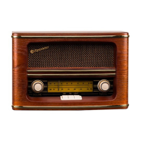
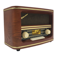
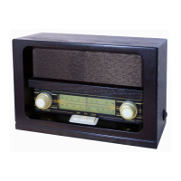
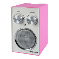
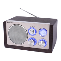
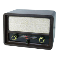
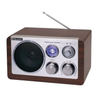
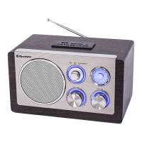
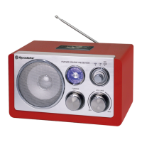
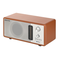
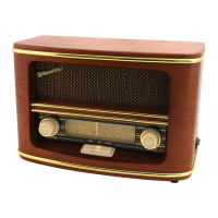
The Roadstar HRA-1500 is a nostalgic wooden music centre radio designed for users who appreciate a classic aesthetic combined with modern functionality. This device serves as a central audio hub, primarily offering radio reception for both AM and FM bands. Its design emphasizes ease of use and a vintage appeal, making it a suitable addition to various home environments.
The core function of the HRA-1500 is to provide radio entertainment. It is equipped to receive both Amplitude Modulation (AM) and Frequency Modulation (FM) broadcasts, allowing users to tune into a wide range of radio stations. The tuning mechanism is designed to be straightforward, likely employing a rotary dial for frequency selection, which contributes to its nostalgic character. The device incorporates an internal AM coil antenna for AM reception and a "tall wire" antenna for FM, ensuring adequate signal capture for clear audio. The internal circuitry is optimized for radio signal processing, including intermediate frequency (IF) stages for both AM and FM, to enhance signal quality and selectivity. Audio output is delivered through an integrated speaker, providing a complete, self-contained listening experience. The power supply is designed for standard AC input, making it convenient for household use.
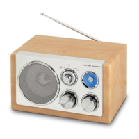
The HRA-1500 is built with user-friendliness in mind, reflecting its "nostalgic" designation. The wooden cabinet not only provides a classic look but also contributes to the acoustic properties of the device. The front panel likely features a prominent tuning knob and a volume control knob, consistent with traditional radio designs. A display lens or window would typically show the selected frequency, aiding in precise tuning. The inclusion of a "function switch" suggests the ability to easily switch between AM and FM modes. The overall control layout is expected to be intuitive, allowing users to quickly power on the device, select their desired band, and tune to a station without complex menus or digital interfaces. The "dial stringing" mechanism, detailed in the manual, is a classic method for connecting the tuning knob to the frequency indicator, offering a smooth and tactile tuning experience. This mechanical aspect is a key part of its nostalgic appeal, providing a tangible connection to older radio technologies. The absence of a DC power source option implies that the device is intended for stationary use within reach of an AC outlet. The physical dimensions and weight suggest it is a tabletop unit, easily placed on a shelf, desk, or cabinet.
The service manual provides comprehensive information for maintaining and repairing the HRA-1500, ensuring its longevity and optimal performance. Safety is a paramount concern, with an "IMPORTANT SERVICE SAFETY INFORMATION" section detailing precautions to prevent electric shock and other hazards during servicing. This includes instructions on checking protective devices, ensuring proper cabinet assembly, and performing leakage current tests. The manual outlines specific "DISASSEMBLY INSTRUCTIONS," starting with the removal of the bottom board by unscrewing eight screws, which grants access to the internal components. This systematic approach facilitates easy access for inspection and repair.
A detailed "DIAL STRINGING" diagram is provided, which is crucial for maintaining the tuning mechanism. This diagram illustrates how the dial spring, dial cord, dial drum, and pointer are interconnected with the tune shaft, enabling technicians to correctly re-string the dial if it becomes loose or broken. This is a common maintenance task for radios with mechanical tuning systems.
"ADJUSTMENT LOCATIONS" and "ALIGNMENT PROCEDURES" are clearly specified for both AM and FM bands. These sections guide technicians through the process of optimizing the radio's reception and audio quality. For instance, the alignment procedures involve using a sweep generator and oscilloscope to adjust various components like IF transformers (T201, T202), variable capacitors (TC1, TC2, TC3, TC4), and inductors (L202, L203, AM Coil). These adjustments ensure that the radio accurately tunes to frequencies and produces clear sound. The use of a plastic screwdriver is recommended for adjustments to prevent damage to sensitive components.
"VOLTAGE CHARTS" are included, providing reference voltage values at specific test points (e.g., IC pins, transistor terminals). These charts are invaluable for troubleshooting, allowing technicians to compare measured voltages against expected values to diagnose component failures or circuit malfunctions.
Furthermore, the manual includes a "WIRING DIAGRAM" and "PRINTED CIRCUIT BOARDS" layouts, which visually represent the electrical connections and component placement within the device. These diagrams are essential for understanding the circuit's operation and for locating specific components during repair. A "SCHEMATIC DIAGRAMS" section offers a detailed electrical blueprint of the radio, showing all components and their interconnections, which is critical for in-depth circuit analysis and fault finding. Finally, an "EXPLODED VIEW/PARTS LIST (CABINET)" provides a breakdown of the physical structure and a list of all cabinet-related parts, aiding in the reassembly process or replacement of external components. This comprehensive documentation ensures that the HRA-1500 can be effectively serviced and maintained throughout its lifespan, preserving its nostalgic charm and functionality.
| Number of batteries supported | 4 |
|---|---|
| Colour | Black |
| Supported radio bands | FM |
| Output Power | 3 W |
| Power source | AC, Battery |
| Battery type | D |
| Weight | 640 g |
| Frequency Range | FM: 87.5-108 MHz, AM: 522-1620 kHz |
| Modulation | FM/AM |
| AC input voltage | 220-240V |