Operating Manual
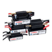
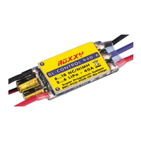
RO-Control NAVY Series
No.8721
No.8722
No.8723
No.8724
Page
3
• With a copper cooling head for good heat dissipation with a water cooling system and
MOSFETs with extremely low internal resistance, this greatly improves overcurrent resistance.
• Innovative software especially for the use of RC boats, with excellent starting and acceleration
behaviour, in connection with an excellent suitability for applications where rapid load changes
occur.
• Two different modes can be set: forward, forward and reverse for different applications
• Several built-in safety precautions: Undervoltage cut-off, overheating protection, protection
against loss of input signal, specially designed for use in RC-boats
• Eight different timing levels programmable, thus compatible with most brushless motors
• Convenient configuration via optional programming card possible
Connect the ESC, motor, receiver, drive battery and servos as shown in the following two pictures.
The three lines from the controller to the motor have no polarity and can be connected freely.
Please check all connections and make sure the motor rotates correctly before proceeding to step
2. If the motor has the wrong direction of rotation, it is necessary to exchange any two connections
between controller and motor.
02. Commissioning a new controller
Connections
Operating Manual
RO-Control NAVY Series
No.8721
No.8722
No.8723
No.8724
Page
4
Figure 1: For the types RO-Control
Navy 30, RO-Control Navy 60 or other
controllers that work with a LiPo battery.
Figure 2: For the types RO-Control
Navy 120, RO-Control Navy 180 or other
controllers that work with two LiPo
batteries.
RO-Control Navy
30 A
RO-Control Navy
60 A
RO-Control Navy
120 A
RO-Control Navy
180 A
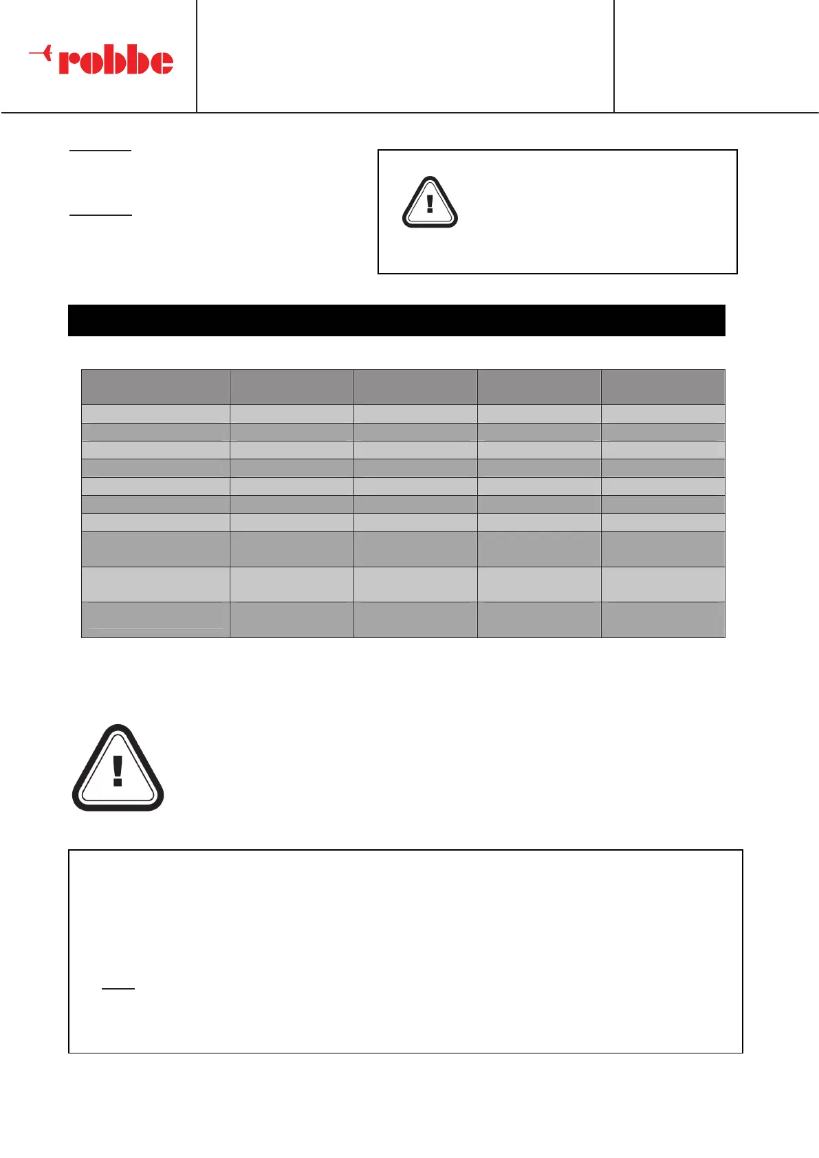
Rated current
30 A 60 A 120 A 180 A
Peak current
180 A 360 A 720 A 1.080 A
BEC Type
linear linear
clocked clocked
BEC Output
6 V / 1 A 6 V / 2 A 6 V / 5 A 6 V / 5 A
LiPo cells
2 - 3 2 - 3 2 - 6 2 - 6
Programming port
unavailable
available available available
Weight
41 g 93 g 150 g 207 g
Water cooling
di = 2,0 mm
da = 4,0 mm
di = 2,0 mm
da = 4,0 mm
di = 3,0 mm
da = 5,4 mm
di = 3,0 mm
da = 5,4 mm
Dimension
54,5 x 28,3 x
18,7 mm
60,5 x 38,5 x
25,6 mm
68,5 x 39,4 x
32 mm
72 x 48 x
36,6 mm
Boat Applicable
length
< 45 cm
length
< 70 cm
length
< 110 cm
length
< 130 cm
Because the different transmitters have different sensor paths, the gas control
stick must be calibrated before the first start-up. This procedure must also be
performed when changing the remote control transmitter and when changing
the settings for the gas channel, such as changing the trim, the dual rate
function and the path setting. Please follow these steps.
Technical Specifications
1. Switch on the transmitter and controller, set the parameters for the gas channel such as Dual
Rate or the travel setting to 100 %. Set the throttle trim to "0". For transmitters without LC
display, set the encoder to maximum and the mechanical trim to the center. For Futaba
transmitters set the direction to "Reverse", for other transmitters it must remain set to
"Normal". We recommend activating a Fail Safe function to ensure that your rc-boat
stops if there is no valid input signal.
Note: If the transmitter is equipped with an ABS function, be sure to disable it. It hinders the
procedure for the calibration of the gas control stick or makes the procedure impossible.
For safety reasons, always keep
yourself and other objects away
from the ship's propeller.
The red cable is the positive pole,
the black cable is the negative
pole.
Throttle Range Calibration
 Loading...