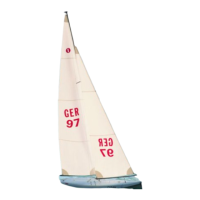
WINDSTAR
13
Bauanleitung, Assembly instructions, Notice de montage
1087
No.
Baustufe 3, die Ruderanlage, Teile 3.1 - 3.10
Nr. Bezeichnung, Maße in mm Stück
3.1 Ruderhebel 1
3.2 Stellring, ø 4 x ø 7 x 5 1
3.3 Schraube, M 3 x 10 1
3.4 Ruder 1
3.5 U-Scheibe, ø 4,3 innen 2
3.6 Ruderkoker, ø 5 x 45 1
3.7 Gestänge, M 2 x 250 1
3.8 Faltenbalg 1
3.9 Röhrchen, ø 10 x 17 1
3.10 Gabelkopf 1
- Den Ruderhebel 3.1 beschneiden und mit einem Stellring 3.2 und
einer Schraube 3.3 versehen.
- Am Schaft des Ruders 3.4 rechtwinklig zum Ruder eine Fläche
anfeilen.
- Die Vorderkante des Ruders gleichmäßig verrunden.
- Eine U-Scheibe 3.5 und den Ruderkoker 3.6 auf den Schaft schie-
ben.
- Die Einheit von unten in den Rumpf setzen und mit dem
Ruderhebel 3.1 - 3.3 und U-Scheibe 3.5 gegen Herausfallen
sichern.
- Durch Sichtprüfung von hinten kontrollieren, ob Ruder und
Schwert zueinander fluchten. Falls erforderlich, die obere Bohrung
für den Ruderkoker nacharbeiten.
- Die Rudereinheit nach oben schieben und den Ruderkoker jeweils
von innen im Rumpf dicht verkleben.
- Das Gestänge 3.7 unter Zugabe von Seifenwasser in den
Faltenbalg 3.8 schieben, das angegebene Maß einhalten.
- Das Röhrchen 3.9 einsetzen und rundum mit Sekundenkleber
sichern.
- Den Gabelkopf 3.10 aufdrehen.
- Das Röhrchen rundum mit Klebstoff einstreichen, Gestänge-
Einheit von innen einsetzen, den Gabelkopf im Ruderhebel ein-
hängen.
- Den Winkel 90° von Ruder zum Ruderhebel und Gestänge prüfen,
falls erforderlich, die Fläche am Ruderschaft nachfeilen.
Stade 3, l’ensemble de gouvernail, pièces 3.1 à 3.10
N° désignation, cotes en mm nombre
3.1 palonnier de gouvernail 1
3.2 bague d’arrêt, Ø 4 x Ø 7 x 5 1
3.3 vis, M 3 x 10 1
3.4 gouvernail 1
3.5 rondelle, Ø 4,3 intér. 2
3.6 jaumière, Ø 5 x 45 1
3.7 tringle, M 2 x 250 1
3.8 soufflet 1
3.9 tube, Ø 10 x 17 1
3.10 chape 1
- Couper le palonnier 3.1 et le munir d’une bague d’arrêt 3.2 et
d’une vis 3.3.
- Limer une surface perpendiculaire au gouvernail au niveau de la
mèche de gouvernail 3.4.
- Arrondir l’arête avant du gouvernail de manière homogène.
- Glisser une rondelle 3.5 et la jaumière 3.6 sur la mèche de gouver-
nail.
- Installer l’unité par le bas dans la coque et la bloquer avec le
palonnier 3.1 à 3.3 et la rondelle 3.5 afin qu’elle ne puisse tomber.
- Contrôler visuellement par l’arrière si le gouvernail et l’aile de déri-
ve sont parfaitement en ligne. Si nécessaire, retravailler le trou du
haut de la jaumière.
- Glisser l’unité de gouvernail vers le haut et bien coller la jaumière
de l’intérieur en appliquant un bon bourrelet de colle pour assurer
l’étanchéité.
- Glisser la tringle 3.7 dans le soufflet 3.8 après l’avoir enduite d’eau
savonneuse, observer la cote indiquée.
- Mettre le tube 3.10 en place et le coller tout autour avec de la colle
cyanoacrylate.
- Visser la chape 3.10.
- Enduire le tube de colle tout autour. Mettre l’unité de tringle en
place de l’intérieur et accrocher la chape dans le palonnier de
gouvernail.
- Vérifier l’alignement de 90° du gouvernail par rapport au palonnier
et à la tringle, si nécessaire rectifier la surface minée de la mèche.
Stage 3, the rudder system, parts 3.1 - 3.10
No. Description, size in mm No. off
3.1 Tiller 1
3.2 Collet, 4 Ø x 7 Ø x 5 1
3.3 Screw, M3 x 10 1
3.4 Rudder 1
3.5 Washer, 4.3 I.D. 2
3.6 Rudder bush, 5 Ø x 45 1
3.7 Pushrod, M2 x 250 1
3.8 Rubber bellows 1
3.9 Tube, 10 Ø x 17 1
3.10 Clevis 1
- Cut down the tiller 3.1 as shown, press a collet 3.2 into it and fit
the screw 3.3 to secure the collet.
- File a flat in the shaft of the rudder 3.4 at right-angles to the plane
of the rudder.
- Round off the front edge of the rudder evenly.
- Fit a washer 3.5 on the shaft followed by the rudder bush 3.6.
- Install this assembly in the hull from the underside and fit the tiller
3.1 - 3.3 and the washer 3.5 to prevent it falling out.
- Sight along the assembly from the stern to check that the rudder
is exactly in line with the keel fin. If necessary adjust the top hole
for the rudder bush.
- Push the rudder assembly upwards and apply glue all round the
rudder bush on the inside to obtain a completely watertight joint.
- Lubricate the pushrod 3.7 with soapy water and slide it into the
rubber bellows 3.8. The pushrod must project by the stated
length.
- Install the tube 3.9 and apply cyano all round to secure it.
- Screw the clevis 3.10 on the pushrod.
- Apply glue all round the tube, install the pushrod assembly from
the inside and connect the clevis to the tiller.
- Check that the rudder is correctly aligned with the tiller (90
degrees) and the pushrod. You may find it necessary to adjust the
flat in the rudder shaft.
 Loading...