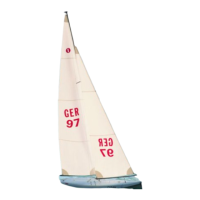
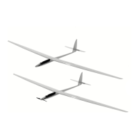
WINDSTAR
23
Bauanleitung, Assembly instructions, Notice de montage
1087
No.
Baustufe 7, Bestücken der Bäume, Teile 7.1 - 7.16
Nr. Bezeichnung, Maße in mm Stück
7.1 S - Haken, ø 1,4 x 12 4
7.2 Wirbellager 1
7.3 Gummiring 2
7.4 Schraube, M 2 x 40 2
7.5 S - Haken, ø 1,4 x 12 1
7.6 Bundbuchse, ø 2,2 x ø 3,6 x 6 2
7.7 Nockbeschlag 2
7.8 Trimmgewicht, ca. 40 g 1 Blei
7.9 Achse, ø 3,5 x 150 1
7.10 S - Haken, ø 1,4 x 12 2
7.11 Stellring, ø4 x ø 7 x 5 1
7.12 Madenschraube, M 3 x 3 1
7.13 Fockstag, ø 1 1 Litze
7.14 Schrumpfschlauch, ø2,4 x 15 1 n.e.
7.15 Hülse, ø1,7 x ø 2,5 x 5 1
7.16 Großbaumlager, 1 x 6 x 33 1
Fockbaum
- 2 S - Haken 7.1 aufbiegen, im Wirbellager 7.2 einhängen und ver-
schließen.
- Wirbellager und hinteren S - Haken 7.1 durch Einschieben des
Arretierungsdrahtes 6.4 im Fockbaum beweglich fixieren.
- Gummiring 7.3 doppelt legen und auf den Fockbaum ziehen.
- Den Nockbeschlag (mit S - Haken) aus den Teilen 7.4 - 7.7 zusam-
mensetzen.
- Ende des Fockbaums leicht zusammendrücken und die Einheit
7.4 - 7.7 einsetzen. Die Bundbuchse muß stramm sitzen.
- Das Trimmgewicht 7.8 mit der Achse 7.9 verkleben.
Trimmgewicht wiederum lackieren.
- Die Achse in den Fockbaum schieben, dabei S - Haken 7.10 und
Stellring 7.11 mit Madenschraube 7.12 mit einsetzen.
- Die Madenschraube 7.12 zur Sicherung anziehen.
- Das Fockstag 7.13 ablängen (15 cm länger als die Vorderkante
des Focksegels).
Hinweis: Bilden von Augen (Dieser Vorgang wiederholt sich an ande-
ren Stellen).
- Zum Bilden eines Auges an einer Litze werden ein Stück
Schrumpfschlauch 7.14 und eine Hülse 7.15 aufgeschoben.
- Das Ende durch den vorderen S - Haken des Fockbaums führen
und in die Hülse fädeln.
- Hülse zusammenpressen, Schrumpfschlauch über das Ende
schieben, um V
erletzungen zu vermeiden.
Großbaum
- 1 S - Haken 7.1 mit dem Arretierungsdraht 6.5 festsetzen.
- Den doppelt gelegten Gummiring 7.3 aufziehen.
- Nockbeschlag aus den Teilen7.4, 7.6 und 7.7 zusammensetzen
und einbauen.
- Das Großbaumlager 7.16 einkleben - Überstand beachten.
Stade 7, équipement des bômes, pièces 7.1 à 7.16
N° désignation, cotes en mm nombre
7.1 crochets, Ø 1,4 x 12 4
7.2 émerillon 1
7.3 élastique 2
7.4 vis, M 2 x 40 2
7.5 crochet, Ø 1,4 x 12 1
7.6 manchon à épaulement, Ø 2,2 x Ø 3,6 x 6 2
7.7 armature de tête du mât 2
7.8 contrepoids, approx. 40 g 1 plomb
7.9 axe, Ø 3,5 x 150 1
7.10 crochet, Ø 1,4 x 12 2
7.11 bague d’arrêt, Ø 4 x Ø 7 x 5 1
7.12 vis sans tête, M 3 x 3 1
7.13 draille de foc, Ø 1 1 fil
métallique
7.14 gaine thermorétractable, Ø 2,4 x 15 1 n.c.
7.15 cosse, Ø 1,7 x 2,5 x 5 1
7.16 vit-de-mulet, 1 x 6 x 33 1
Bôme de foc
- Ouvrir deux crochets 7.1, les accrocher à l’émerillon 7.2 et les
refermer.
- Fixer l’émerillon et crochet arrière 7.1 à la bôme de foc en instal-
lant le fil d’arrêt 6.4, l’émerillon doit cependant conserver sa mobi-
lité.
- Installer l’élastique 7.3 en double et l’enfiler sur la bôme de foc.
- Assembler l’armature de tête du mât (avec crochet) à partir des
éléments 7.4 à 7.7.
- Écraser légèrement l’extrémité de la bôme de foc et mettre l’unité
7.4 à 7.7 en place. Le manchon à épaulement doit être bien tendu.
- Coller le contrepoids 7.8 à l’axe 7.9.
Le peindre également.
- Glisser l’axe dans la bôme de foc en mettant simultanément le
crochet 7.10 et la bague d’arrêt 7.11 avec vis sans tête 7.12 en
place.
- Serrer la vis sans tête 7.12 pour bloquer l’ensemble.
- Couper la draille de foc 7.13 à la longueur indiquée (15 cm de plus
que l’arête avant du foc).
À noter: former un œillet (cette procédure est reprise plusieurs fois
ultérieurement).
- Pour former un œillet sur un filin, y enfiler un morceau de gaine
thermorétractable 7.14 et une cosse 7.15.
- Passer l’extrémité par le crochet avant de la bôme de foc et enfi-
ler la cosse.
- Écraser la cosse, glisser la gaine thermorétractable sur l’extrémi-
té pour éviter toute blessure.
Bôme de grand voile
- Bloquer le crochet 7.1 avec le fil d’arrêt 6.5.
- Mettre l’élastique double 7.3 en place.
-
Assembler la têtièr
e à partir des pièces 7.4, 7.6 et 7.7 et l’installer
.
- Coller le vit-de-mulet 7.16 - observer le dépassement indiqué.
Stage 7, fitting out the booms, parts 7.1 - 7.16
No. Description, size in mm No. off
7.1 S-hook, 1.4 Ø x 12 4
7.2 Swivel 1
7.3 Rubber band 2
7.4 Screw, M2 x 40 2
7.5 S-hook, 1.4 Ø x 12 1
7.6 Flanged bush, 2.2 Ø x 3.6 Ø x 6 2
7.7 Peak fitting 2
7.8 Trim weight, approx. 40 g 1 Lead
7.9 Shaft, 3.5 Ø x 150 1
7.10 S-hook, 1.4 Ø x 12 2
7.11 Collet, 4 Ø x 7 Ø x 5 1
7.12 Grubscrew, M3 x 3 1
7.13 Forestay, 1 Ø 1 Braided
wire
7.14 Heat-shrink sleeving, 2.4 Ø x 15 1 N.I.
7.15 Sleeve, 1.7 Ø x 2.5 Ø x 5 1
7.16 Main boom support, 1 x 6 x 33 1
Jib boom
- Open up two S-hooks 7.1, connect the swivels 7.2 and close them
again.
- Slip the retaining wire 6.4 through the jib boom and attach the swi-
vels and the rear S-hook 7.1. These parts must be free to move.
- Double up the rubber band 7.3 and push it onto the jib boom.
- Assemble the peak fitting (with S-hook) from parts 7.4 - 7.7.
- Gently squeeze the end of the jib boom and insert the peak fitting
assembly 7.4 - 7.7. The flanged bush must be a tight fit.
- Glue the trim weight 7.8 to the shaft 7.9.
Paint the trim weight.
- Push the shaft into the jib boom, fitting the S-hook 7.10 and the
collet 7.11 (with grubscrew 7.12) at the same time.
- Tighten the grubscrew 7.12 to secure these parts.
- Cut the forestay 7.13 to length (15 cm longer than the front edge
of the jib).
Note: forming loops (this procedure is required repeatedly from this
point on):
- To form a loop in a piece of braided wire first slip a piece of heat-
shrink sleeving 7.14 and a crimp sleeve 7.15 onto the wire.
- Pass the end of the wire through the front S-hook in the jib boom
and thread it back into the crimp sleeve.
- Squeeze (crimp) the sleeve and push the heat-shrink sleeve over
the end to avoid injury from the sharp wire.
Main boom
- Secure one S-hook 7.1 with the retaining wire 6.5.
- Pull the doubled-over rubber band 7.3 into position.
-
Assemble the peak fitting fr
om parts 7.4, 7.5 and 7.7 and install it.
- Glue the main boom support 7.16 in place, noting the amount by
which it should project.
 Loading...