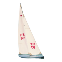
WINDSTAR
27
Bauanleitung, Assembly instructions, Notice de montage
1087
No.
Baustufe 9, Vorbereiten des Stells, Teile 9.1 - 9.11
Nr. Bezeichnung, Maße in mm Stück
9.1 Großsegel 1
9.2 Schraube, M 2 x 6 2
9.3 U-Scheibe, ø 2,2 innen 2
9.4 Achterstagverstellung, ø 1 1 Takelgarn
9.5 Klemmschieber 1
9.6 Achterstag, ø 1 1 Litze
9.7 Schrumpfschlauch, ø 2,4 x 15 2 n.e.
9.8 Hülse, xø 1,7 x ø 2,5 x 5 2
9.9 Toppbeschlag 1
9.10 S-Haken, ø 1,4 x 12 1
9.11 Fock 1
- Großbaum am Mast einhängen.
- Niederhalter einbauen.
- Großsegel 9.1 von oben einziehen und mit Schraube 9.2 und U-
Scheibe 9.3 an der Nock befestigen.
- Die Achterstagverstellung
am Schraubhaken des Heckspiegels
aus den Teilen 9.4 und 9.5 herstellen - Zeichnung beachten.
Takelgarn ungefähr auf 150 mm einstellen. Der Klemmschieber
sollte sich dabei etwa in der Mitte befinden.
- Das Achterstag 9.6 mit einem gebildeten Auge (9.7, 9.8) am
Toppbeschlag 9.9 befestigen.
- Toppbeschlag in den Mast einsetzen. Achterstag bis Unterkante
Mast ablängen.
- Am unteren Ende des Achterstags mit Schrumpfschlauch 9.7,
Hülse 9.8 und S-Haken 9.10 ein Auge bilden. Länge des
Achterstags endgültig so einstellen, daß der S-Haken mit der
Nock des Großbaums abschließt.
- Fockstag in die Tasche der Fock 9.11 einziehen und Fock mit
Schraube 9.2 und U-Scheibe 9.3 am Nockbeschlag befestigen.
Stade 9, préparation de la voilure, pièces 9.1 à 9.11
N° désignation, cotes en mm nombre
9.1 grand voile 1
9.2 vis, M 2 x 6 2
9.3 rondelle, ø 2,2 intér. 2
9.4 dispositif de réglage de l’étai arrière, Ø 1 1 fil
9.5 coulisse 1
9.6 étai arrière, Ø 1 1 fil
métallique
9.7 gaine thermorétractable, Ø 2,4 x 15 2 n.c.
9.8 cosse, Ø 1,7 x Ø 2,5 x 5 2
9.9 têtière 1
9.10 crochet, Ø 1,4 x 12 1
9.11 foc 1
- Accrocher la bôme de grand voile au mât.
- Installer le hale-bas.
- Enfiler la grand voile 9.1 par le haut et la fixer avec la vis 9.2 et la
rondelle 9.3 à l’armature.
- Réaliser le dispositif de réglage de l’étai arrière
au niveau du cro-
chet de l’arrière tableau à partir des pièces 9.4 et 9.5. Tenir
compte des indications du schéma. Régler le filin à environ 150
mm. La coulisse doit alors se trouver approximativement au
milieu.
- Fixer l’étai arrière 9.6 avec un œillet (9.7, 9.8) à la têtière 9.9.
- Installer la têtière dans le mât. Couper l’étai au niveau de l’arête
inférieure du mât.
- À l’extrémité inférieure de l’étai arrière former un œillet avec un
morceau de gaine thermorétractable 9.7, une cosse 9.8 et un cro-
chet 9.10. Régler la longueur de l’étai arrière définitivement de
sorte que le crochet coïncide avec l’armature de la bôme de grand
voile.
- Tirer l’étai de foc dans le capelage d’étai du foc 9.11 et fixer le foc
avec la vis 9.2 et la rondelle 9.3 à l’armature.
Stage 9, preparing the rig, parts 9.1 - 9.11
No. Description, size in mm No. off
9.1 Mainsail 1
9.2 Screw, M2 x 6 2
9.3 Washer, 2.2 I.D. 2
9.4 Backstay adjustor, 1 Ø 1 Thread
9.5 Sliding clamp 1
9.6 Backstay, 1 Ø 1 Braided
wire
9.7 Heat-shrink sleeving, 2.4 x 15 2 N.I.
9.8 Crimp sleeve, 1.7 Ø x 2.5 Ø x 5 2
9.9 Masthead fitting 1
9.10 S-hook, 1.4 Ø x 12 1
9.11 Jib 1
- Connect the main boom to the mast.
- Install the kicking strap.
- Draw the mainsail 9.1 into the mast from the top and secure it at
the peak using the screw 9.2 and washer 9.3.
- Make up the backstay adjustor at the transom screw hook from
parts 9.4 and 9.5 as shown in the drawing. Cut the thread to a
length of about 150 mm. The sliding clamp should be about half-
way along it.
- Form a loop (9.7, 9.8) in the backstay 9.6 and attach it to the mast-
head fitting 9.9.
- Press the masthead fitting into the mast. Cut the backstay to the
length of the bottom edge of the mast.
- At the bottom end of the backstay form a loop with the heat-shrink
sleeve 9.7, the crimp sleeve 9.8 and the S-hook 9.10. The final
length of the backstay is correct when the S-hook coincides with
the peak of the main boom.
- Draw the forestay into the seam of the jib 9.11 and connect the jib
to the peak fitting using the screw 9.2 and washer 9.3.
 Loading...