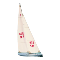
WINDSTAR
9
Bauanleitung, Assembly instructions, Notice de montage
1087
No.
- Den Mastunterzug 1.1 rechtwinklig zur Rumpf-Längsachse auf-
legen, mit der Mastschraube 1.6 zentrieren. Die ø 3 mm Löcher für
die Schraubhaken übertragen und ebenfalls bohren.
- Die Einnietmuttern 1.5 in die 4 mm Löcher der Teile 1.1 - 1.3 ein-
ziehen und mit Sekundenkleber sichern. Den oberen Überstand
wegschleifen.
- Die Mastschraube 1.6 von unten in den Unterzug 1.1 kleben.
- 6 Schraubhaken 1.7 mit Muttern 1.8 und U-Scheiben 1.9 verse-
hen. Gewindegänge einölen.
- Den Unterzug 1.1 mit Klebstoff einstreichen und einsetzen. Zwei
Schraubhaken rechts und links eindrehen.
- Die U-Scheibe 1.10 und die Mutter 1.11 an der Mastschraube
anbringen.
- Ebenso die Verstärkungen 1.2 anbringen, wobei die seitlichen
Teile mit den Schrauben M 2,5 x 10 (10.10) gesichert werden.
- Den Hilfsdraht „HD“ durch die mittlere, der 3 vorderen
Rumpfbohrungen zur Decksöffnung ziehen.
- Die Verstärkung 1.3 mittig aufstecken, Draht abwinkeln.
- Verstärkung mit Klebstoff einstreichen. Den Draht nach vorn zie-
hen und bis zum Aushärten mit 2 Schraubhaken sichern, damit die
Verstärkung innen anliegt.
- Draht entfernen.
- Die Schotrolle aus den Teilen 1.12 - 1.14 zusammensetzen und
mit dem vorderen Schraubhaken 1.7 montieren.
- Die Verstärkungen 1.15 - 1.18 einkleben, wobei die Verstärkung
1.15 ebenfalls mit dem Hilfsdraht „HD“ eingezogen werden muß
- Die Löcher für die Schraubösen 1.19 durchbohren und Ösen ein-
drehen.
- Den Gummipuffer 1.20 aufrauhen und auf die Rumpfspitze kleben.
- Installer le support de mât 1.1 perpendiculairement à l’axe longi-
tudinal du bateau et le centrer avec la vis de mât 1.6. Reporter et
percer les trous de 3 mm de Ø pour les crochets filetés.
- Planter les écrous à riveter 1.5 dans les trous de 4 mm des pièces
1.1 à 1.3 et les bloquer avec de la colle cyanoacrylate. Limer la
saillie supérieure.
- Coller la vis de mât 1.6 par-dessous dans le support 1.1.
- Munir les crochets à vis 1.6 des écrous 1.8 et des rondelles 1.9,
huiler les filets.
- Enduire le support 1.1 de colle et le mettre en place. Serrer deux
crochets filetés à droite et à gauche.
- Installer la rondelle 1.10 et l’écrou 1.11 sur la vis de mât.
- Installer de la même manière les renforts 1.2 en les bloquant laté-
ralement avec les vis M 2,5 x 10 (10.10).
- Passer la corde à piano „HD“ de montage dans les trous médians
avant de la coque vers l’ouverture du pont.
- Planter le renfort 1.3 au milieu et couder la corde à piano.
- Enduire le renfort de colle. Tirer la corde à piano vers l’avant et
bloquer avec 2 crochets à vis jusqu’à ce que la colle soit sèche
afin que le renfort s’appuie à l’intérieur.
- Retirer la corde à piano.
- Assembler la poulie d’écoute à partir des pièces 1.12 à 1.14 et la
monter avec le crochet fileté avant 1.7.
- Coller les renforts 1.15 à 1.18 en introduisant également le renfort
1.15 avec la corde à piano de montage „HD“.
- Percer les trous pour les œillets à vis 1.19 et mettre les œillets en
place.
- Poncer le tampon de caoutchouc 1.20 et le coller sur la pointe de
la coque.
- Place the mast girder 1.1 in position at right-angles to the hull cen-
treline, and fit the mast screw 1.6 to centre it. Mark the position of
the holes for the screw-hooks and drill them 3 mm Ø.
- Press the rivet nuts 1.5 into the 4 mm holes in parts 1.1 - 1.3 and
secure each one with a drop of cyano. Sand back the excess
material where it projects at the top.
- Glue the mast screw 1.6 to the underside of the girder 1.1.
- Fit the nuts 1.8 and washers 1.9 on the six screw-hooks 1.7 and
apply a drop of oil to the threaded shanks.
- Apply glue to the girder 1.1 and position it carefully. Fit the two
screw-hooks into it, one on each side.
- Attach the washer 1.10 and the nut 1.11 to the mast screw.
- Attach the reinforcements 1.2 in the same way; the side parts are
secured with M2.5 x 10 screws (10.10).
- Locate the three holes in the hull, pass the jig wire „HD“ through
the central one and run it as far as the deck opening.
- Fit the reinforcement 1.3 on the wire, set it central and bend the
end of the wire over at an angle.
- Apply glue to the reinforcement, then pull the wire forward to bring
the reinforcement into position. Fit the two screw-hooks to ensu-
re that the reinforcement makes good contact with the inside of
the deck. Remove the screw-hooks when the glue has set hard.
- Remove the jig wire.
- Assemble the sheet pulley from parts 1.12 - 1.14 and install it
using the front screw-hook 1.7.
- Glue the reinforcements 1.15 - 1.18 in place, again using the jig
wire „HD“ to pull part 1.15 into position.
- Drill the holes for the ring-screws 1.19 and fit them in the holes.
- Roughen up the joint surface of the rubber buffer 1.20 and glue it
to the point of the bow.
 Loading...