7
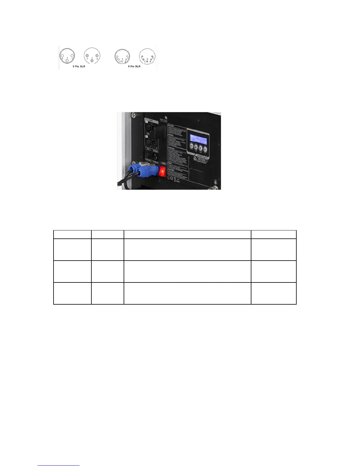
DMX Connector Pin Assignment
The machine provides a 3- or 5-pin XLR connector for DMX connection. The diagram below indicates pin
assignment information.
DMX Operation
Making the DMX Connection – Connect the machine to a DMX controller or to one of the machines in the
DMX chain. The machine uses a 3-pin or 5-pin XLR connector for DMX connection, the connector is located
on the front of the machine.
Address Setup – Use control menu to set DMX address. The machine occupies 3 control channels. The starting
address is dened as the rst channel from which the machine will respond to the controller. Always double
check to make sure there are no overlapping channles in order to control the machine correctly.
DMX chart
Channel Value Function Type of control
1
0-127
128-255
Mode selection
Faze Mode
Fog Mode
step
proportional
2
0-5
6-255
Faze/fog Output
Output Off
Output 21-100%
step
proportional
3
0-5
6-255
Fan
Fan speed at 20%
Fan speed 21-100%
step
proportional
7. Service and maintenance
Do not allow the machine and uid to become contaminated.
Regularly ll distilled water to uid tank and run the machine to clean the system. After cleaning, rell Robe
fog uids into uid tank and make sure machine can produce fog properly.
It is recommended to run the machine on a monthly basis in order to achieve best performance and output
condition.
Excessive dust, liquid and dirt built up will degrade performance and cause overheating
Pin Function
1 Ground
2 Data -
3 Data +