INSTALLATION DATA
2374-510
UNIVERSAL AIR PRESSURE
SENSING SWITCH
191 E. North Avenue
Carol Stream Illinois 60188 USA
Customer Service Telephone 1.800.304.6563
Customer Service Facsimile 1.800.426.0804
HVACCustomerService@Invensys.com
Invensys™ and Robertshaw
®
are trademarks of Invensys
plc., its subsidiaries and/or affiliated companies. All
other brands mentioned may be the trademarks of their
respective owners.
www.Uni-Line.com
www.InvensysControls.com
©2011 Invensys Controls
5/11 - LTNS2000008 00
For Technical Service
Telephone 1.800.445.8299
Facsimile 1.630.260.7294
TechnicalService@Invensys.com
(1) eld adjustable switch
(1) black set point adjustment screw
(1) hexagon key wrench
(5) color-coded springs
(8) color-coded orices
(1) half strap mounting bracket
(1) angle ("L") bracket
(1) mounting screw for optional brackets
(2) #6 x ⅜" mounting screws for optional brackets
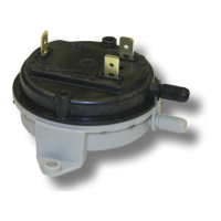
The Robertshaw
®
2374-510 Air Pressure Sensing Switch
has a glass-lled polycarbonate housing containing a
sensing diaphragm and an integral snap-acting switch
with three male 90° quick-connect terminals. The switch
can sense positive, negative or differential air pressure.
The eld adjustable set point range of this switch is
0.10" W.C. to 10.0" W.C. Using the switch accessories
contained in this kit, the switch can be applied to a
wide variety of residential and light commercial HVAC
applications.
Calibration requires a manometer (not included in the kit)
as well as the included
7
⁄32" hex wrench.
1. Establish the set point as follows. Referring to Table 2 in
this manual, select the appropriate spring for the required
set point range. Insert the spring into the center well of
the mounting pan (light gray side of the switch housing).
2. Insert the black set point adjustment screw, and rotate
it manually until the threads are engaged.
3. Connect the switch to a manometer. Using the
7
⁄32"
hex wrench provided in the kit, turn the adjustment screw
in small increments until the desired set point is reached.
Turn the screw clockwise to increase the set point or
counterclockwise to decrease the set point. For precise
calibration, conrm the set point at actual operating
temperature with a manometer. Following precise
calibration, if desired, seal the adjusting screw using a
UV curable adhesive/sealant.
Using the (2) #6 x ⅜" mounting screws included in the
kit, mount via the integral foot bracket (see Fig. 1) or, via
either of the optional brackets (see Figs 4 & 5) included
in the kit. If using one of the optional brackets, attach it
to the switch with the self-tapping screw provided before
mounting the switch. Select a mounting location free
from vibration. Mount with the diaphragm in any vertical
plane. Avoid mounting with the sample line connections
directed upward.
The snap switch has three ¼" 90° male quick connect
terminals. Before pressure is applied to the diaphragm,
the switch contacts are in the deactivated position as
shown in Figure 2.
Integral sample line connectors, located on both sides
of the diaphragm, accept
3
⁄16" ID exible tubing. See
Figure 3. The High or Positive inlet (P1) is black and the
Low or Negative inlet (P2) is gray. Connect the sample
lines as follows:
Connect the sample line to P1;
P2 remains open to the atmosphere.
Connect the sample line to P2;
P1 remains open to the atmosphere.
Connect higher negative sample
to P2; lower sample to P1.
Connect higher positive sample
to P1; lower sample to P2.
Connect positive
sample to P1; connect negative sample to P2.
Some applications require a delayed switching action
after set point is reached. The delay is created by
inserting an orice plug into either or both of the sample
line connectors to restrict air ow. Eight orice plugs in
four color-coded sizes are included in the kit as shown
in Table 3. Note that the measuring device and the air
switch must both contain the same size restricting orice in
order to obtain an accurate measurement of the set point.