Do you have a question about the Robertshaw 5318B and is the answer not in the manual?
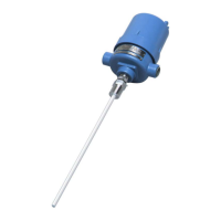
Provides a general overview of the Robertshaw Model 5318B Level-Tek RF capacitance level switch and its capabilities.
Explains how to identify specific instrument models based on designation and variations listed in tables.
Details the environmental operating conditions including temperature, humidity, vibration limits, and weight specifications.
Outlines performance characteristics such as temperature coefficient, time delays, and selectable control ranges.
Covers electrical specifications including supply voltage, power consumption, and control relay contact ratings.
Describes the standard and optional enclosure types, including their certifications and materials.
Lists the compliance and certifications, such as UL, CAN/CSA, and RoHS directives.
Provides initial installation steps, including checking for shipping damage and selecting an appropriate location.
Details probe selection criteria, types (insulated/bare), and installation methods considering vessel wall and nozzle length.
Guides the installation of rod-type probes horizontally for optimal level detection and control.
Explains the procedure for installing rod-type probes vertically to match the desired level detection point.
Covers methods for mounting the instrument itself, either directly on the probe or remotely via a cable assembly.
Describes how to mount the Level Tek II instrument directly onto the installed probe assembly.
Details the process for remotely mounting the instrument using a separate cable assembly for extended reach.
Provides detailed instructions and diagrams for making all necessary electrical connections, including supply power and relay contacts.
Introduces operation, controls, indicators, and explosion-proof caution.
Details the LED indicators, LCD display, and navigation pushbutton switches for user interaction.
Introduces the initial setup process and mentions the default factory setup values for the instrument.
Guides users on selecting the appropriate control range based on probe and media characteristics for accurate measurement.
Explains the user's option to display measurements as RAW input or a converted linear value (CNVRTD).
Details how to access and modify various instrument setup values using the navigation switches.
Guides through accessing setup values, selecting display format, sampling rate, fail-safe mode, and time delays.
Introduces the various calibration procedures available for the instrument to match the vessel/process.
Covers Adjustable Differential, Alarm++, Alarm+, Alarm--, Alarm-, and Control calibration methods for different applications.
Describes how to make minor adjustments (up to 10% in 0.1% increments) to setpoints after initial calibration.
Covers selecting, adjusting, and returning to normal display mode after setpoint tweaking.
Details the procedure for restoring the instrument's settings and calibration to the original factory defaults.
Explains the function of the status LED as an indicator of the instrument's operational health and troubleshooting.
Introduces and details error codes 01 (Reserved), 02 (Too High), 03 (Too Low), 04 (Low Setpoint Reversed), and 05 (High Setpoint Reversed).
| Brand | Robertshaw |
|---|---|
| Model | 5318B |
| Category | Switch |
| Language | English |