Do you have a question about the Robertshaw 300-225 and is the answer not in the manual?
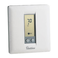
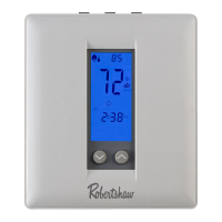
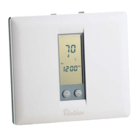
Describes the thermostat's advanced LCD screen for user interface.
Feature allowing secure access to thermostat controls.
Instructions for setting the current date and time on the thermostat.
Function to temporarily or indefinitely hold the current temperature setting.
Instructions for inputting program schedule days and times.
Function to temporarily or indefinitely hold the current temperature setting.
Specific locations to avoid for proper thermostat operation and accuracy.
Step-by-step guide on how to detach the thermostat unit from its base.
Instructions for installing the thermostat subbase on the wall.
Configuration option for setting 2 or 4 daily program periods.
Setting to control fan operation based on occupancy and program periods.
Feature to prevent unauthorized changes by locking the keypad.
Switch to control fan operation with heating systems (electric vs. gas/oil).
Switch setting for heat pump systems, differentiating standard and add-on configurations.
Setting for single or multistage compressor systems.
Function of LED #1 to indicate filter change requirement.
Function of LED #2 to indicate service requirement.
Configuration for add-on heat pump systems and fossil fuel kits.
Step-by-step instructions for setting high (HibP) and low (LobP) balance points.
Instructions for installing and using the plastic lock to secure the thermostat cover.
Procedure for reattaching the thermostat unit to its subbase after installation or maintenance.
Requirement and connection of load resistors for specific equipment loads.
Important note regarding transformer requirements when a jumper is removed.
Note on using a 24 Volt DC supply with the thermostat.
Notes on DC operation for specific older unit models.
Instructions for connecting transformers in a dual transformer system.
Critical instruction for setting DIP switch #4 on model 300-226.
Notes on DC operation for specific older unit models.
Instructions for connecting transformers in a dual transformer system.
Important note regarding transformer requirements when a jumper is removed.
Note on using a 24 Volt DC supply with the thermostat.
Notes on DC operation for specific older unit models.
Instructions for connecting transformers in a dual transformer system.
Requirement and connection of load resistors for specific equipment loads.
Template for recording desired heating and cooling temperatures and times.
Using the copy feature to duplicate program times to other days.
How to set a temporary temperature override for a 3-hour period.
Temporary override function for locked keypads, lasting 1 hour.
How to set a constant temperature hold indefinitely.
Instructions to switch the temperature display between Fahrenheit and Celsius.
Instructions to switch the clock display between 12-hour and 24-hour formats.
How the thermostat behaves and retains settings during power interruptions.
How to view the outdoor temperature using an optional remote sensor.
Reminder about the AM/PM indicator when setting times.
Critical note on maintaining a minimum temperature difference between heating and cooling.
Explanation of thermostat behavior when cooling setpoint is close to heating setpoint.
How to check the programmed schedule settings.
Procedure for modifying existing programmed times and temperatures.
The adjustable temperature range for heating and cooling modes.
The minimum temperature difference before the system cycles on/off.
Note on the thermostat's electronic circuitry design.
Troubleshooting for a single transformer system when the fault indicator is ON.
Wiring configuration for separate RH and RC wires in a dual transformer system.
Wiring configuration for single RH/RC wires in a dual transformer system.
Details of the product warranty, coverage, and exclusions.
| Brand | Robertshaw |
|---|---|
| Model | 300-225 |
| Category | Thermostat |
| Language | English |