Do you have a question about the Robertshaw RS8210 and is the answer not in the manual?
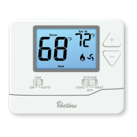
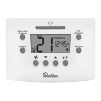
Details the primary display screen, its readouts, and indicators.
Explains ON and AUTO settings for continuous or system-cycled fan operation.
Describes selecting HEAT, COOL, or OFF modes for HVAC system operation.
Instructions for using the plus/minus buttons to adjust the desired temperature.
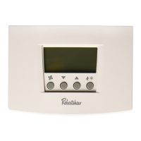
Identifies buttons used for setting up programming options.
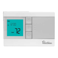
Diagram and labels for display elements like time, temperature, and status indicators.
Notes the thermostat supports four programmable time periods per day.
Provides caution for battery replacement and instructions for accessing the battery compartment.
Explains the filter reminder feature and how to reset it.
Step-by-step guide to setting the current time and day of the week.
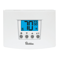
Simple instructions for adjusting the desired set temperature.
Adjustable setting for air filter change reminders, from OFF to 2000 hours.
Allows calibration of the displayed room temperature by +/- 3°F.
Sets minimum run time for the compressor (OFF, 3, 4, or 5 minutes).
Configures or disables a delay to protect the compressor from short cycling.
Adjustable setting for cooling system turn-on threshold, 0.2°F to 2°F.
Adjustable setting for heating system turn-on threshold, 0.2°F to 2°F.
Option to select Fahrenheit (°F) or Celsius (°C) for temperature display.
Choice between 24-hour or 12-hour format for displaying time.
Setting to specify whether the system uses electric or gas heat.
Designation for the terminal controlling the auxiliary heat relay.
Designation for the terminal controlling the compressor relay.
Designation for the terminal controlling the fan relay.
Terminal for heat pump reversing valve energized in cooling mode.
Designation for the 24VAC power input terminal.
Designation for the common wire connection, if applicable.
Terminal for heat pump reversing valve energized in heating mode.
Designation for the emergency heat relay terminal.
| Brand | Robertshaw |
|---|---|
| Model | RS8210 |
| Category | Thermostat |
| Language | English |