Fig. 10-3 Fig. 10-4
Order 1
I
i
Item
Procedure
Remarks
Tool
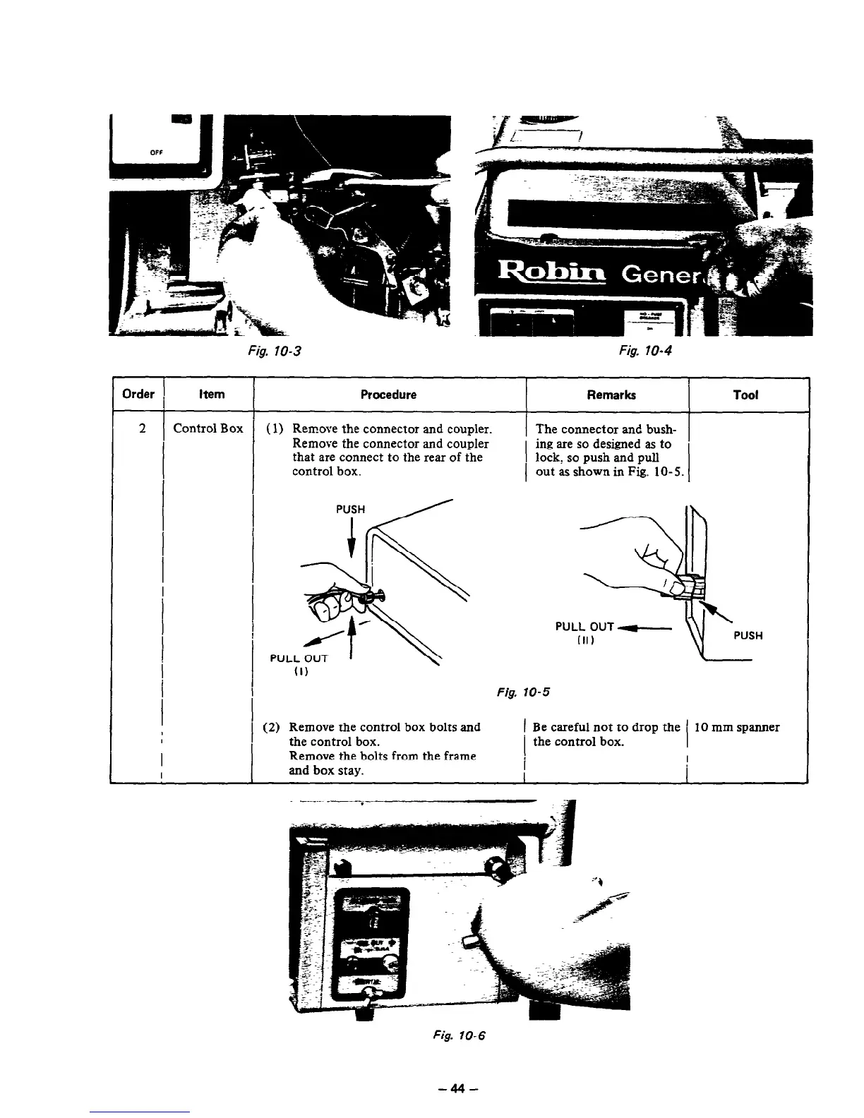
2 Control Box
(1) Remove the connector and coupler.
The connector and bush-
Remove the connector and coupler
ing are so designed as to
I
that are connect
to
the rear of the
I
lock, so push and pull
control box.
out as shown in Fig. lo- 5.
I
I
I
I
(1)
Fig. 10-5
(2) Remove the control box bolts and
1 Be careful not to drop the ’ 10 mm spanner
the control box.
the control box.
Remove the bolts from the frame
and box stay.
I
Fig. 10-6
-44-