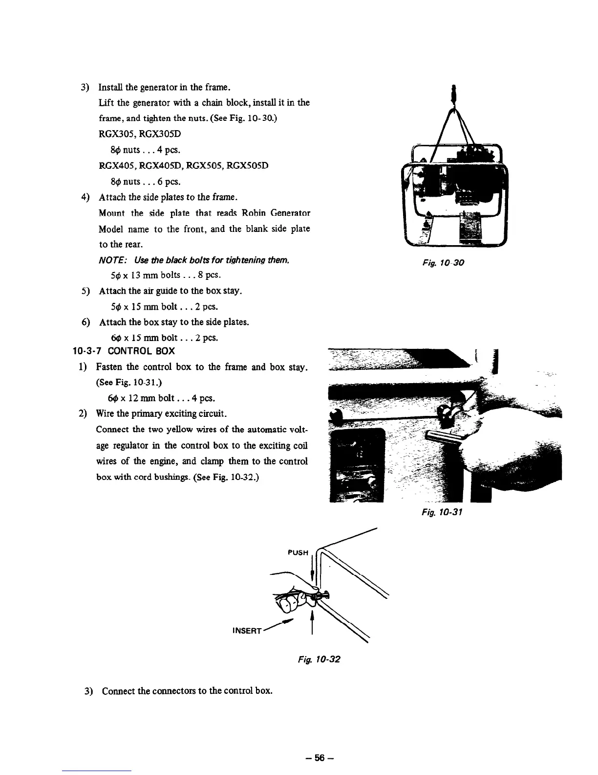
3) Install the generator in the frame.
Lift the generator with a chain block, install it in the
frame, and tighten the nuts. (See Fig. 10-30.)
RGX305, RGX305D
B@nuts...4pcs.
RGX405, RGX405D, RGX505, RGX505D
89 nuts . . .6 PCS.
4) Attach the side plates
to the
frame.
Mount the side plate that reads Robin Generator
Model name to the front, and the blank side plate
to the rear.
NOTE: Use the black bolts for tightening them.
jt$ x 13 mm bolts _ . -8
PCS.
5) Attach the air guide to the box stay.
5@xl5mmbolt...2pcs.
6) Attach the box stay to the side plates.
6r#~x15mmbolt...2pcs.
10-3-7 CONTROL BOX
1)
2)
Fasten the control box to the frame and box stay.
(See Fig. 10-3 1.)
6@xl2mmbolt...4pcs.
Wire the primary exciting circuit.
Connect the two yellow wires of the automatic volt-
age regulator in the control box to the exciting coil
wires of the engine, and clamp them to the control
box with cord bushings. (See Fig. 10-32.)
Fig. lo-30
Fig. lo-31
Fig. lo-32
3) Connect the connectors to the control box.
-56-