EasyManua.ls Logo

Robinson Willey Sahara - User Manual

Robinson Willey Sahara
24 pages
Print Icon
To Next Page IconTo Next Page
Loading...
1
SERVICE AND INSTALLATION
INSTALLATION, SERVICING & OPERATING INSTRUCTIONS
L E AV E T H E S E I N S T R U C T I O N S W I T H T H E U S E R
IMPORTANT - This fire is for use on Natural Gas ONLY (G20)
SAHARA with Safeguard
Sahara (Pewter) G.C. No. 32 689 38
Sahara (Antique Bronze) G.C. No. 32 689 39
RADIANT/CONVECTOR
GAS FIRE
Sahara
300001229_2
D
ON
T FOR
G
ET
T
o register your guarantee!
C
al
l
03
4
4
8
79 3
5
8
8
THIS LEAFLET IS INTENDED TO HELP YOU UNDERSTAND AND USE YOUR NEW GAS FIRE EFFICIENTLY.
PLEASE READ THESE INSTRUCTIONS BEFORE USING THE FIRE AND KEEP FOR FUTURE REFERENCE.

Other manuals for Robinson Willey Sahara

Question and Answer IconNeed help?

Do you have a question about the Robinson Willey Sahara and is the answer not in the manual?

Summary

Sahara with Safeguard Installation, Servicing & Operating Instructions

Technical Data and Specifications

Heat Input and Output Ratings

Details on the fire's maximum and minimum heat input and maximum output.

Site Requirements: Fireplace and Surround

Fireplace Opening and Surround Clearances

Requirements for non-combustible material and clearances around the fireplace opening.

Site Requirements: Hearth Mounting

Site Requirements: Wall Mounting

Site Requirements: Brick Chimney

Site Requirements: Pre-Cast Flue

Site Requirements: Twin-Walled Flues

Installation Procedure: Unpacking and Closure Plate

Fitting the Closure Plate

Detailed steps and important notes for fitting the closure plate to the fireplace opening.

Installation: Mounting and Flue Checks

Flue Pull Verification

Procedure to check for correct draught in the flue before fitting the fire.

Installation: Fire Preparation and Spigot Restrictor

Installation: Fitting Spigot and Gas Fire

Hearth and Wall Mounting the Fire

Steps for physically mounting the gas fire onto a hearth or wall.

Gas Supply Connection and Testing

Making the Gas Connection

Procedure for connecting the fire to the main gas supply using appropriate tubing.

Gas Soundness and Pressure Testing

Tests for gas tightness and correct burner pressure, including FSD operation.

Ignition System Check

Verifying the functionality of the piezo or battery spark ignition system.

Fire Assembly and Component Fitting

Spillage Test Procedure

User Information and Safety Checks

Flame Supervision Device Explanation

Explaining the FSD and ODS function and when to call an engineer.

Servicing Instructions: Component Removal

Gas Tap and FSD Assembly Servicing

Procedure for servicing or replacing the gas tap and flame supervision device.

Servicing: Pilot System and Ignition Components

How to Light and Operate the Fire

Piezo Spark Ignition Procedure

Step-by-step guide for lighting the fire using the piezo ignition system.

Battery Spark Ignition Procedure

Instructions for lighting the fire using the battery powered ignition.

Overview

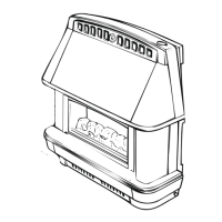
The device described in the manual is the SAHARA with Safeguard Radiant/Convector Gas Fire, manufactured by Robinson Willey. It is designed for heating residential spaces and operates on Natural Gas (G20) only.

Function Description:

The SAHARA with Safeguard is a radiant convector gas fire that provides heating through both radiant heat and convection. It features a duplex burner and a duplex gas tap with a flame supervision device (FSD) for safety. Ignition is achieved via an integral piezo or battery-powered electronic spark, activated by turning the gas tap knob. A key safety feature is the Oxygen Depletion Sensing (ODS) pilot, which is designed to shut off the fire if the oxygen level in the room falls below a prescribed level or if there's a poor flue pull. The fire offers multiple heat settings, allowing users to adjust the radiant output. It can be installed as either a hearth-mounted or wall-mounted appliance, provided the installation adheres to specific non-combustible material and clearance requirements.

Important Technical Specifications:

  • Fuel Type: Natural Gas ONLY (G20)
  • Gas Pressure: 20 mbar (8in w.g.)
  • Burner Type: Aerated Duplex Burner
  • Injector: 2 off, Marked RY/220
  • Pilot Burner: OP NG9031 OR NG9077
  • Ignition: Piezo or battery-powered ignition integral with tap
  • Control Tap: Duplex Plug Type with flame supervision device
  • Inlet Connection: Rp 1/4 (1/4 BSP)
  • Overall Dimensions (mm):
    • Height: 640
    • Width: 727
    • Depth: 232
  • Height to top of flue spigot: 412 mm
  • Weight: 24 Kg
  • Heat Input (GROSS):
    • Maximum Input: 6.04 kW (20,600 Btu/h)
    • Minimum Input: 1.55 kW (5,290 Btu/h)
  • Maximum Output: 4.78 kW (16,320 Btu/h)
  • Setting Pressure (Cold): 17.0 mbar ± 1 (6.8in w.g. ± 0.4)
  • Efficiency: 78.8% (as specified in BS 7977-1:2002), exceeding the minimum requirement of 63%. This value can be used for the UK Government's Standard Assessment Procedure (SAP) for energy rating of dwellings.
  • Flue Requirements:
    • Suitable for conventional brick chimney, pre-cast flues, various proprietary flues, and metal flue boxes conforming to BS 715.
    • Minimum effective flue height: 3 metres (10ft).
    • Brick Chimney (228mm x 228mm): Cross-section area not less than 120cm² (19in²). Flue spigot restrictor may be required for chimney heights over 4.3m (14ft) with good draught.
    • Pre-cast Flue (198mm x 67mm): Minimum effective height 3m (10ft), flueways at least 198mm x 67mm or equivalent cross-sectional area with no dimension less than 63mm (2½in). Fireplace opening width 305-457mm, height 441-630mm, depth at least 100mm. Flue spigot restrictor not used.
    • Twin-Walled Flues (BS 715): Double-walled or insulated metal box with a twin-walled or insulated flue at least 125mm (5in) in diameter. Minimum effective height 3m (10ft). Opening depth at least 165mm.
  • Clearances:
    • Combustible material side wall: No less than 508mm (20in) from radiant source, or suitably protected.
    • Clearance from case side for access/servicing: 50mm (2in) each side.
    • Battery replacement (RH side): Around 115mm clearance.
    • Wooden shelf above fire: Underside of 150mm (6in) deep shelf must be at least 115mm (4½in) above fire top. For deeper shelves, increase shelf height by 13mm (½in) for every 25mm (1in) increase in depth.
  • Hearth Mounting: Non-combustible, at least 13mm (½in) thick, 710mm (28in) wide by 305mm (12in) deep, preferably 50mm (2in) above floor level.
  • Wall Mounting: Non-combustible wall, top of spigot opening in closure plate at least 488mm above finished floor level.
  • Dressguard: Conforms to BS 1945:1991 and satisfies Heating Appliances (Fireguards) (Safety) Regulations 1991. It is for preventing risk of fire or injury from burns and should not be permanently removed. It does not give full protection for young children, the elderly, or the infirm, for whom a guard conforming to B.S. 8423 is recommended.

Usage Features:

  • Control Knob Settings: The control knob, located on the top right-hand side of the fire, has settings for OFF, PILOT, 1, 2, 3, and 4.
    • PILOT: Pilot flame only (consumes 0.2kW gas).
    • 1: Centre 2 radiants on low.
    • 2: Centre 2 radiants on full on.
    • 3: Centre 2 radiants on full on, outer 2 on low.
    • 4: All 4 radiants on full on.
  • Lighting Procedure (Piezo Spark Ignition): Push and turn the control knob anti-clockwise from OFF to PILOT position. Hold for 1-2 seconds, then continue to PILOT. Two 'clicks' will be heard, and the pilot should light. Keep the knob pushed in for 10 seconds to activate the FSD. Release the knob; the pilot should remain lit. If not, repeat. Once the pilot is established, turn to the desired setting.
  • Lighting Procedure (Battery Spark Ignition): Depress and release the knob at PILOT position several times until the pilot lights. Keep the knob depressed for 10 seconds to activate the FSD. Release the knob; the pilot should remain lit. Once the pilot is established, turn to the desired setting.
  • Lighting with a Taper: In case of ignition spark failure, light a taper, apply it to the pilot, then press and turn the control knob anti-clockwise to PILOT. Hold for 10 seconds after the pilot lights.
  • Turning Off: Push the control knob slightly and turn it clockwise to the OFF position. Alternatively, turn to PILOT to leave the pilot running.
  • Relighting a Hot Fire: Wait 3 minutes before attempting to relight a hot fire.
  • Safety Features: Flame Supervision Device (FSD) and Oxygen Depletion Sensing (ODS) pilot. If the fire repeatedly shuts off, it indicates a fault that must be rectified by a competent person.
  • Initial Use: A slight smell may be noticed when the new fire is first lit, which should dissipate after a few hours.

Maintenance Features:

  • Annual Servicing: The fire should be serviced annually by a competent person (Gas Safe registered Engineer) for continuing efficient and safe operation.
  • Cleaning:
    • Do not clean while the fire is warm.
    • General cleaning: Damp, soapy cloth, followed by polishing with a soft cloth.
    • Chromed parts: May be cleaned with a metal polish.
    • Radiants: Dusted with a soft brush.
    • Canopy: Light dusting only; do not polish.
    • Abrasive cleaners should never be used.
  • Radiant Changing (User Replaceable):
    • Ensure the fire is cold.
    • Remove the dressguard by withdrawing prongs from side reflectors and pulling downwards.
    • Remove radiants by lifting upwards and outwards.
    • Replace radiants by inserting top first beneath the firebox canopy, ensuring they sit behind the front lip of the radiant support.
    • Replace dressguard by inserting vertical prongs into top reflector holes, then re-engaging side prongs.
  • Control Knob (User Replaceable): Part No. 138 913 (820863).
  • Battery Replacement (for battery ignition models):
    • The ignition spark generator (containing a size AA battery) is at the lower rear RH side.
    • Unscrew the cap anti-clockwise from the battery holder.
    • Remove the old battery and insert a new one, 'flat end first' (negative terminal).
    • Replace the cap carefully to avoid cross-threading.
    • Note: Consumable items like batteries are not covered by the guarantee.
  • Pilot Lint Filter Cleaning:
    • If the pilot flame is floppy yellow or difficult to light, the lint filter may need cleaning.
    • Clean by vacuuming dust and lint from the filter.
    • If vacuuming is insufficient, a Gas Safe registered engineer must investigate.
    • To remove the lint filter, slide it downward after disconnecting the pilot gas supply tube. Refit by pushing up against the pilot bracket, ensuring it is crimped in place.
  • Professional Servicing (by competent persons):
    • Removal of Outer Components: Fender, gas tap knob, outer case, and canopy.
    • Gas Tap/FSD Assembly: Removal and replacement involves disconnecting spindle extension, piezo igniter spark lead/battery leads, union nut at inlet, thermocouple, pilot feed union nut, and the large nut securing the gas tap to the burner. Injectors must be transferred to a new tap.
    • Injectors: Unscrew from the tap and replace.
    • Burner Assembly: Involves removing spindle extension, disconnecting gas tap inlet union nut, piezo igniter spark lead/battery leads, and three brass nuts holding the burner. The gas tap and pilot are transferred to the new burner.
    • Spark Generator Replacement: Disconnect leads, slacken knurled locking ring, and slide out the generator. Fit replacement in reverse order, transferring the battery or fitting a new one.
    • Pilot Filter: Located in the outlet from the gas tap. Prise out with a pin and insert a new one.
    • Pilot Assembly: An atmosphere sensing device, must be replaced as a complete unit if faulty. Troubleshooting involves checking pilot flame, gas supply, thermocouple, magnet unit in gas tap, room ventilation, and combustion product clearance/spillage.
    • Piezo Igniter: Not renewable as a separate item; if faulty, the gas tap/FSD assembly must be replaced.

The manual emphasizes the importance of professional installation and servicing by Gas Safe registered engineers in accordance with all relevant British Standards and Building Regulations. It also includes a "Benchmark Checklist" for installers to complete, ensuring compliance and validating the product's warranty.

Robinson Willey Sahara Specifications

General IconGeneral
BrandRobinson Willey
ModelSahara
CategoryIndoor Fireplace
LanguageEnglish

Related product manuals