D 630 V1112 45
NederlandsFrançaisEnglishDeutsch
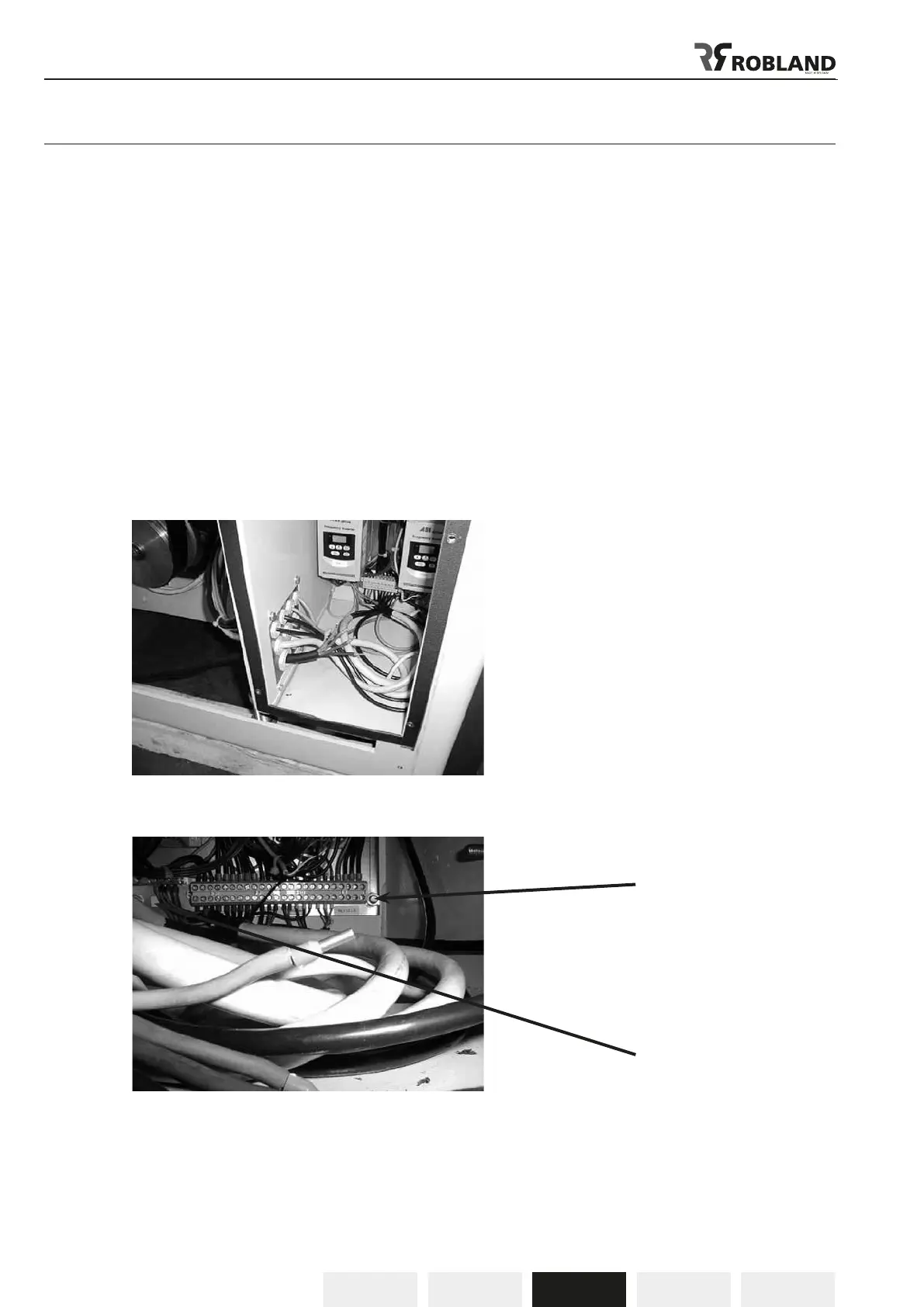
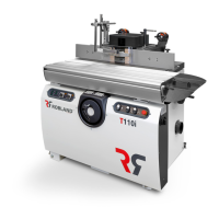
Electrical connections (Fig.2 - 2.2)
The electrical connections must be carried out by a qualied electrician who is able to
calculate the exact needed wire section and caliber of fuses.
- Check that the mains voltage of your machine corresponds with the voltage in your workshop.
- Open the electrical connection box at the side of the machine (g, 2).
- Connect the three phases to the terminals marked L1, L2, L3 (g,2 bis).
- The neutral conductor (blue) it is to be connected to the terminal N.
- Connect the earthing (green-yellow) to the terminal marked with the earth symbol PE.
- Check rst if the spindle runs free and if all protections are mounted before starting up the machine.
- If the rotation direction of the spindle is not correct, the leads L1, and L2 must be exchanged.
- The rotation direction of the spindle is anti-clockwise: left, seen from the side of the machine with the
dust chute open.
ATTENTION:
The machine is equipped with overload protection, and should the motor be shut-off by this protection,
it is necessary to wait for a few minutes untill the overload has cooled down, and resets itself.
Fig.2
Fig.2.2
3 phases L1, L2, L3
Neutral N
Earth