www.spiercetech.com
3
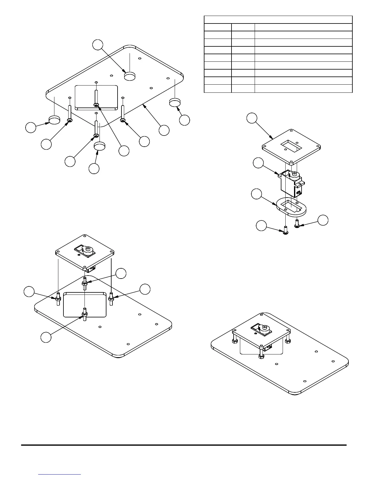
meArm Assembly Manual v0.4
PARTS LIST
PART NUMBER
QTY
ITEM
Base Plate
11
Rubber Foot
4
2
M3 x 20mm Screw43
M3 Nut
44
Pivot Servo Plate
15
Servo Retainer
1
6
9 Gram Servo
17
M3 x 8mm Screw28
2
2
2
2
3
3
3
3
1
5
7
6
8
8
4
4
4
4
Step 1: Place (4) Rubber Feet on the bottom side of the Base Plate
Step 2: Insert (4) M3 x 20mm Screws through bottom side of the base plate
Step 3: Insert Servo into top side of Servo Retainer
Step 4: Insert Servo into bottom side of Pivot Servo Plate
Step 5: Insert (2) M3 x 8mm Screws through bottom of Servo
Retainer and thread them into the Pivot Servo Plate.
Note: The M3 x 8mm Screws will form their own threads into the
undersized Servo Retainer Plate. Do not over tighten the screws
or it will strip the mating holes.
Step 6: Thread (1) M3 Nut half way onto each of the (4) M3 x 20mm Screws
Step 7: Screw each of the M3 x 20mm Screws into the mating holes on the
Pivot Servo Plate until the end of the screw is flush with the top of
the Pivot Servo Plate
Step 8: Tighten the M3 Nuts the rest of the way down onto
the Base Plate
 Loading...