www.spiercetech.com
5
meArm Assembly Manual v0.4
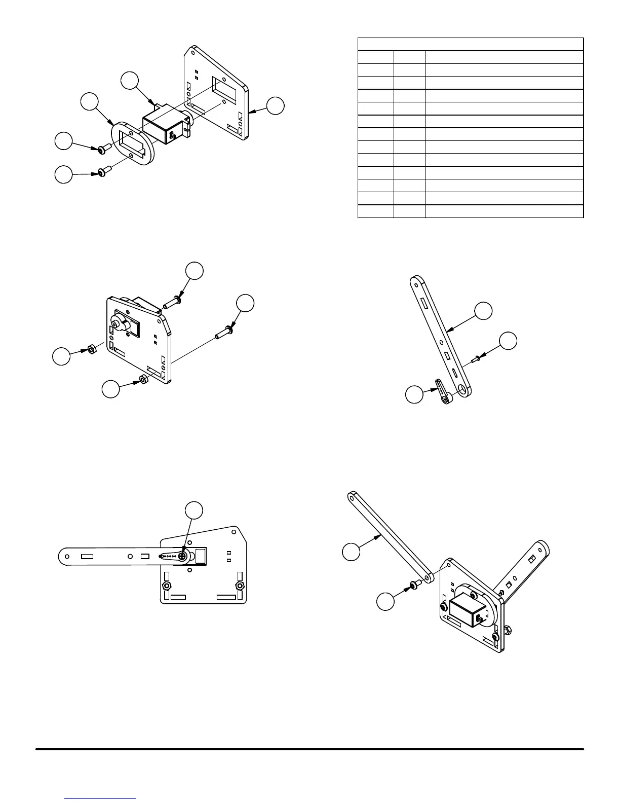
PARTS LIST
PART NUMBERQTYITEM
M3 Nut2
1
Servo Retainer12
9 Gram Servo
1
3
M3 x 8mm Screw2
4
Parallel Linkage15
M3 x 6mm Screw16
Servo Single Arm
17
M3 x 12mm Screw28
Right Arm Base Joint
19
Right Arm Servo Plate
1
10
Servo Screw111
Servo Mount Screw112
Step 18: Slide Servo Retainer over the bottom end of the Servo
Step 19: Slide Servo into Right Arm Servo Plate
Step 20: Insert (2) M3 x 8mm Screws into the Servo Retainer and then
screw them into the Left Arm Servo Plate
8
8
1
1
12
9
7
11
5
6
Step 21: Insert (2) M3 x 12mm screws into back side of
Right Arm Servo Plate
Step 22: Thread (1) M3 Nut onto each M3 x 12mm screw
until nut is flush with the end of the screw
Step 23: Attach the Servo Arm to the Right Arm Base Joint
using (1) of the Servo Mount Screws supplied with the
Servo.
Step 24: Press the Arm Base Joint assembly onto the Servo and then
gently rotate the Servo Arm counter clockwise by hand until it stops.
After it has stopped, remove the Arm Base Joint assembly from the
Servo and position it as shown in the picture above.
Step 25: Insert the Servo Arm Screw that is supplied with the Servo
10
3
2
4
4
Step 26: Insert (1) M3 x 6mm Screw into the Parallel Linkage
and thread it into the Right Arm Servo Plate
 Loading...