Do you have a question about the RoboteQ FBL2360 and is the answer not in the manual?
Lists different FBL2360 models with their channel count, amperage, voltage, Ethernet, and STO support.
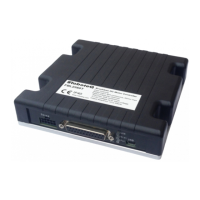
Details how power connections are made using faston tabs on the controller's back.
Emphasizes imperative wiring instructions for safe and trouble-free operation, highlighting mandatory thick black lines.
Explains the need for a high-power emergency switch or contactor for safety.
Discusses ESD protection compliance and methods to maximize it by connecting the heatsink to the battery negative terminal.
Warns that this wiring must only be done on the single channel version (FBL2360S) to prevent damage.
Details using an external safety contactor for applications where property damage or injury can occur.
Advises on proper mounting for adequate cooling to achieve published amp ratings, emphasizing direct contact with a metallic surface.
Explains how to connect Hall Sensors using a special 10-pin Molex Microfit 3.0 connector on the front.
Describes using absolute angle sensors with SPI interface on specific models, utilizing the Hall Sensor connector.
Details connecting SSI absolute angle sensors, noting their availability on specific product versions.
Explains connecting resolvers or magnetic sensors with sin/cos voltage outputs using analog inputs.
Notes that resolver wiring is similar to Sin/Cos sensors, with an added excitation signal.
Details connecting RC Radio, microcomputers, joysticks, and other sensors via the DB25 connector.
Shows the factory default pin assignments for analog, RC, and RS232 connections.
Covers enabling Analog commands, USB, and RS485 communication protocols for system interaction.
Covers Ethernet, Status LED patterns, and Battery Backed Clock features for monitoring and functionality.
Explains how the controller measures motor amps and relates RMS current to DC equivalent in different modes.
Details STO as a safe method for switching the controller to a no-torque state, requiring redundant inputs.
Describes the use of standard 250mils AMP FASTON Tabs for high current and secure power connections.
Lists critical parameter limits that should never be exceeded to prevent permanent damage.
Provides detailed electrical specifications for the power stage operating at ambient temperature.
Details specifications for various signal types including output voltages, current thresholds, and input impedances.
Lists parameters like command latency, PWM frequency, and RS232 baud rate.
Provides details on scripting capabilities like flash memory, program lines, and execution speed.
Lists thermal parameters such as case temperature, power dissipation, thermal resistance, and humidity.
Details STO input levels, response time, operating and storage temperatures, and IP rating.
Provides physical specifications including weight and power connector width, along with dimensional diagrams.
The RoboteQ FBL2360 is a high-current, dual or single-channel controller designed for brushless DC motors, offering a comprehensive suite of features for precise motor control in various applications. This versatile device can operate in multiple modes to accurately sense rotor position and sequence power to the motor's three windings, ensuring smooth and continuous rotation. It leverages both Hall sensor and Encoder data to compute speed and measure traveled distance using a 32-bit counter, enabling operation in open or closed-loop speed, position, or torque modes.
The FBL2360 is equipped with several Analog, Pulse, and Digital I/Os that can be remapped for various functions, including command inputs, feedback, and limit switches. It supports a wide range of command sources, such as RC radios, analog joysticks, wireless modems, and microcomputers. For mobile robot applications, the controller's two motor channels can be operated independently or mixed for coordinated movement and steering. Connectivity is further enhanced by a CAN bus interface, allowing up to 127 controllers to be networked at speeds up to 1 Mbit/s over a single twisted pair.
Safety is a paramount concern, and the FBL2360 incorporates numerous features to ensure reliable and safe operation. The controller's functionality can be extensively automated and customized through Basic Language scripts. For ease of use, it can be configured, monitored, and tuned in real-time using RoboteQ's free PC utility. Furthermore, the device supports field upgrades, allowing users to download the latest operating software from Roboteq to access new features.
Key features of the FBL2360 include support for USB, Serial, 0-5V Analog, or Pulse (RC radio) command modes, with an auto-switch function based on user-defined priority. It includes one RS232 serial port and a CAN bus interface with multiple protocol support, as well as RS485. An optional Ethernet interface is also available for enhanced connectivity. The controller features built-in dual 3-phase high-power drivers capable of handling up to 60A per motor, with output channels that can be paralleled to drive a single motor at up to 120A.
The FBL2360 supports multiple motor operating modes, including Trapezoidal with Hall Sensors, Sinusoidal with Encoders, and Sinusoidal with Hall Sensors. It also offers support for absolute angle encoders, including sin/cos analog, SSI (A & T version), and Resolver (A & T version). Field Oriented Control is available in Sinusoidal modes, providing full forward and reverse motor control with four-quadrant operation and regeneration support. The controller operates from a single 10V-60V power source.
For enhanced safety, the FBL2360T version includes Safe Torque Off (STO) support, certified to UL 61800-5-1. It features programmable current limits up to 60A (or 120A in single-channel mode) per motor to protect the controller, motor, wiring, and battery. Separate connectors are provided for Hall Sensors, and the device offers accurate speed and odometry measurement using Hall Sensor or Encoder data.
Additional features include up to 8 Analog Inputs for command or feedback, up to 8 Pulse Length, Duty Cycle, or Frequency Inputs, and up to 10 Digital Inputs for functions like Deadman Switch, Limit Switch, Emergency Stop, or general user inputs. It supports up to 2 Quadrature Encoders and provides 4 general-purpose 24V, 1.5A outputs for brake release or accessories. Users can select min, max, center, and dead band in Pulse and Analog modes, along with exponentiation factors for each command input. Trigger actions can be set if Analog, Pulse, or Hall counter capture falls outside user-selectable ranges (soft limit switches).
The FBL2360 supports open-loop or closed-loop speed control, closed-loop position control with encoder, Hall sensors, analog or pulse/frequency feedback, and torque mode. A PID control loop is integrated, along with built-in Battery Voltage and Temperature sensors. An optional backup power input ensures safe controller operation even if main motor batteries are discharged. A Power Control wire allows external microcomputers or switches to turn the controller On or Off, and the output stage consumes no power when motors are stopped. A regulated 5V output is available for powering RC radios, RF Modems, sensors, or microcomputers.
Maintenance features include separate programmable acceleration and deceleration for each motor, ultra-efficient 2.5 mOhm ON resistance MOSFETs (1.25 mOhm on Single Channel), and stall detection with selectable triggered action if current falls outside user-selected range. The controller offers short circuit protection, overvoltage and undervoltage protection, and a watchdog for automatic motor shutdown in case of command loss. Overtemperature protection and a diagnostic LED further enhance reliability. The ABS plastic enclosure with a heat-conducting bottom plate ensures efficient heat sinking, allowing operation without a fan in most applications. It is dustproof and weather-resistant with an IP40 rating. The device uses 0.25" Faston tabs for power wiring and has a compact form factor. It operates in a wide temperature range and includes easy configuration, tuning, and monitoring using the provided PC utility. Field-upgradeable software allows for installing the latest features via the internet.
The controller is designed and built to comply with UL and IEC specifications and standards. For critical applications, an external safety contactor is recommended to prevent uncontrolled motor operation. Proper mounting is essential for heat dissipation, ensuring the controller's bottom surface makes direct contact with a metallic chassis or cabinet for effective conduction cooling. Hall sensor connections are made via a dedicated 10-pin Molex Microfit 3.0 connector. For single-channel wiring, motor wires must be connected to both output tabs of the same letter, utilizing Channel 1's Encoders and/or Hall sensors.
For absolute angle encoders, the FBL2360 and FBL2360S models can use motors with SPI interface sensors. The SPI signals are found on the 10-pin Molex connector, with the controller issuing clock and select signals and capturing serial data from each sensor. Analog Sin/Cos absolute encoders are also supported, utilizing 4 high-speed analog inputs on the 25-pin connector to capture absolute angle position from resolvers or magnetic sensors with sin/cos voltage outputs.
The FBL2360 also includes a battery-backed clock and variables feature, providing accurate time/date stamping for status and error reports. This feature ensures that user input variables remain even when the unit is powered off. Customers are required to install the BR-1225 coin-style battery for the clock functionality.
The STO (Safe Torque Off) feature, available in T-versions, provides a safe method for switching the controller into a state where no torque is generated, regardless of normal or faulty operation. When enabled, two digital inputs (DIN1 and DIN2) are remapped as STO1 and STO2. Both inputs must receive a 6V to 30V signal for the Power MOSFETs to be energized. The controller performs a self-check of the STO circuit at power-on and whenever STO inputs transition to high. If either input is below 1V, the controller's outputs are disabled. The STO circuit is verified and validated, offering a trusted safety mechanism. By factory default, STO functionality is disabled and can be enabled by removing a jumper on the PCB.
The FBL2360 measures motor amps with precision, while battery amps are estimated. The controller is rated based on RMS Amps, with a clear relation between RMS current and DC Equivalent in Sinusoidal and Trapezoidal modes. In sinusoidal mode, DC equivalent amps are the resultant from torque (Iq) and quadrature (Id) vectors. In trapezoidal mode, they are the DC amps flowing through the two active coils at any given time.
The controller's power motor and battery connections are made via standard 250mils (6.35mm) AMP FASTON Tabs, providing high current and secure connections. For maximum current handling, AWG8 wires are recommended. While FASTON connectors offer a tight fit, it is recommended to route wiring to prevent outward pulling. For frequent disconnections, Positive Lock connectors from TE Connectivity or equivalent are suggested.
The FBL2360 also supports Ethernet communication on E-versions, with a connection port on top of the unit. Both TCP and Modbus TCP protocols are supported, though Serial is preferred for accessing native commands. Status LED flashing patterns provide visual cues for operating or exception status, indicating idle, RS232/USB mode, RC Pulse mode, Analog mode, short detected, overheat, under or over voltage, and power stage off. Additional status information can be obtained by monitoring the controller with the PC utility.
| Type | Brushless DC Motor Controller |
|---|---|
| Max Current | 60A per channel |
| Weight | 0.5 kg |
| Motor Channels | 2 |
| Encoder Inputs | 2 |
| Input Voltage | 12-36V |
| Communication Interface | USB, CAN |
| Control Modes | Open Loop, Closed Loop Speed, Closed Loop Position |
| Voltage Range | 12V - 36V |
| Operating Temperature | -40 to 85 °C |