17
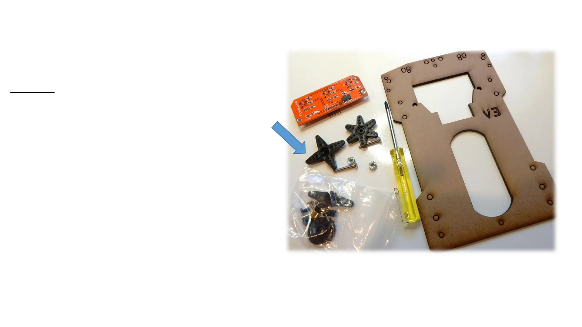
Parts:
(2) metal locking nuts
(2) 3/4 screws
Red line following sensor
Lower laser cut chassis
star screwdriver
Servo horns from one of your 360
rotation servos
We will use the plastic servo
horns as spacers to ensure the
line following sensor is low
enough or closer to the floor so
it can see the dark/white colors
Servo
Horns
Step 3: Assembling the Line Following Sensor