Installation, Start-Up, Adjustment and Maintenance Manual
44
® ® ®
® ® ®
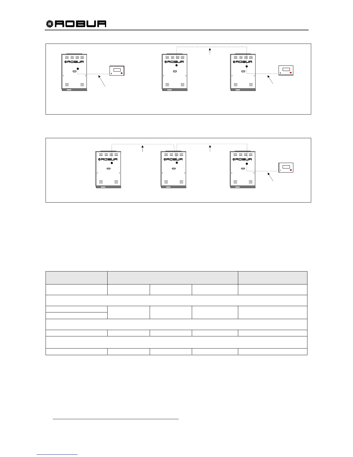
Figure 20 – EXAMPLE CONNECTION OF DDC TO SINGLE ACF60-00 UNIT (2 nodes network) AND TO N.2
ACF60-00 UNITS CONNECTED ON THE SAME HYDRONIC SYSTEM (3 nodes network).
Figure 21 – EXAMPLE CONNECTION OF DDC TO N.3 ACF60-00 UNITS CONNECTED ON THE SAME HYDRONIC
SYSTEM (4 nodes network).
CAN-BUS wire connection
If the network connection is max 650 ft cable long and has max 6 nodes (e.g.: 5 ACF60-00 + 1 DDC) a
simple shielded wire 3 x 18 AWG is required.
For major lengths, the CAN-BUS wire should be compatible with Standards Honeywell SDS.
The next Table shows some examples of these wires, according to the total length of the wire itself:
CABLE TYPE AND
MODEL
COLOR AND SIGNAL
MAX DISTANCE COVERED
ft
ROBUR NETBUS
BLACK = H WHITE = L BROWN = GND 1475
Honeywell SDS 1620
BELDEN 3086A
TURCK type 530
BLACK = H WHITE = L BROWN = GND 1475
DeviceNet Mid Cable
TURCK type 5711 BLUE = H WHITE = L BLACK = GND 1475
Honeywell SDS 2022
TURCK type 531 BLACK = H WHITE = L BROWN = GND 656
Table 17 – EXAMPLE OF TYPES OF WIRES USED FOR CAN-BUS
NOTE: “GND” is the common signal wire, and NOT a ground connection.
Take the CAN-BUS wire of suitable length for the connection between DDC and the unit and, for every
network or CAN-BUS wire segments (from a node to another) cut sheath of the wire from both terminal for
about 3” length and connect them to the proper nodes, on the electronic control board (S61) or on DDC.
4
C
AYF 60-119
ACF60-00
2
CAN-BUS wire
(see SPARE PARTS)
1
DDC
 Loading...