Electrical installer
Installation, use and maintenance manual – M gas unit heater
25
4
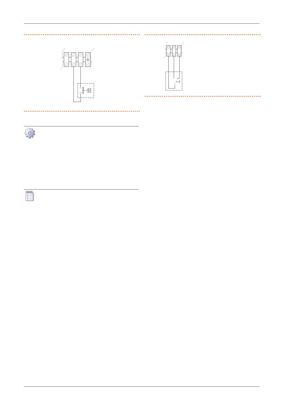
Figure4.3 Connection of external request for gas unit heater
start/stop management
Z9 External request (e.g. thermostat, timer, switch, ...)
9 1110
4.4.2.2 Summer/winter mode management
How to connect the external request for
summer/winter mode management
1. Access the electrical board of the appliance according
to the Procedure 4.2
p.23
.
2. Remove the 28 temporary jumper between 1-3 termi-
nals on the internal terminal block.
3. Connect the voltage-free contact of the external re-
quest, using a 3x1 mm² cable, to 1, 2, 3 terminals of the
terminal block, as shown in Figure 4.4
p.25
.
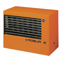
The cable may not be longer than 20 metres.
Figure4.4 Summer/winter switch connection
Z1 Summer/winter
switch
1 2 3
4.4.2.3 Control of multiple gas unit heaters with a
single external request
Through a suitable connection to the terminals described
above, it is possible to manage the specic function on
more than one gas unit heater using a single external
request.
The centralised management of the on/o switch can be
carried out as described in Figure 4.5
p.26
, using a time
programmer and several room thermostats. The presence
of the room thermostats serving each generator allows to
activate the generator itself only when the specic area
has a real need for heat, avoiding waste of energy. The
presence of a time programmer makes it possible to sub-
ordinate the ignition of the heater, even in the presence
of a request from the room thermostat, to a centralised
consent.