6
INSTALLA
TION
-TWEETERS
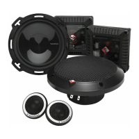
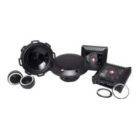
Wiring Tweeter to Crossover
1. Use illustrations for proper connection.
2. Be sure to maintain speaker polarity
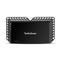
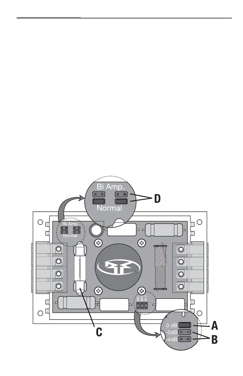
Setting Crossover
A 0dB Tweeter Level matches the amplitude of the tweeter to the speaker
B -2dB/-4dB Tweeter Level reduces the amplitude of the tweeter -2dB or -4dB lower than the midrange.
(ex. ideal for tweeters located high in door panels and midranges located low in the kick panel)
C Replaceable Tweeter Protection Bulb acts as a fuse to protect against overload. If the bulb burns out,
remove the burned out bulb and insert a new bulb (12 volt, 10 watts) into the retainer clips.
D Bi-Amping –The Power components have the ability run separate channels of amplification to the
tweeter and speaker on the same crossover.This can be done to allow for more control of the output
of each individual speaker.
NOTE:When NOT bi-amping the crossover, connect to the MID inputs only.The jumpers must be in the
"Normal" position.
To Bi-amp
1. Make sure the system is off.
2. Connect the speaker outputs from the amplifier that will drive the speaker to the MID inputs on the
crossover.Then connect the speaker outputs from the amplifier that will drive the tweeter to the TW
inputs on the crossover.
3. Move the jumpers from the “Normal” position to the “Bi Amp” position.
View from bottom of crossover
 Loading...