English-10
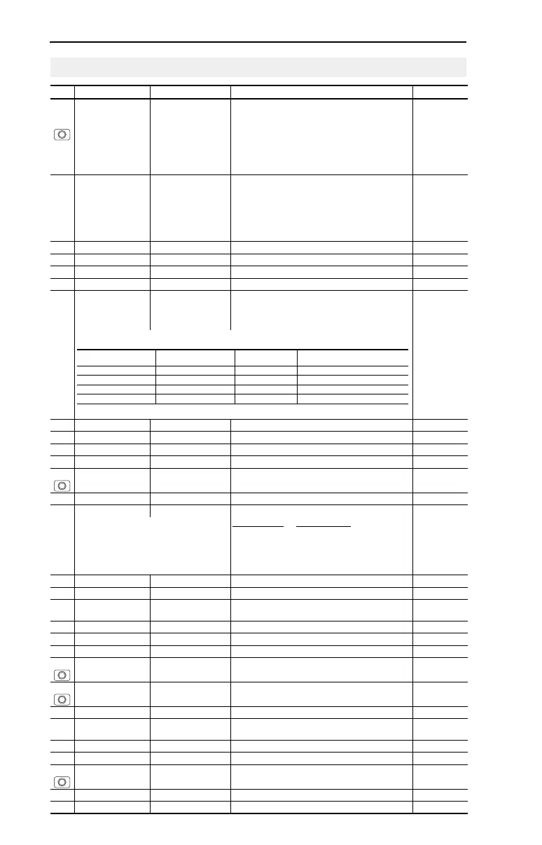
Advanced Group Parameters
No. Parameter Min/Max Display/Options Default
A051
A052
[Digital In1 Sel]
I/O Terminal 05
[Digital In2 Sel]
I/O Terminal 06
0/26 0 = “Not Used”
1 = “Acc 2 & Dec 2”
2 = “Jog”
3 = “Aux Fault”
4 = “Preset Freq”
5 = “Local”
6 = “Comm Port”
7 = “Clear Fault”
8 = “RampStop,CF”
9 = “CoastStop,CF”
10 = “DCInjStop,CF”
11 = “Jog Forward”
12 = “Jog Reverse”
13 = “10V In Ctrl”
14 = “20mA In Ctrl”
26 = “Anlg Invert”
4
A055 [Relay Out Sel] 0/21 0 = “Ready/Fault”
1 = “At Frequency”
2 = “MotorRunning”
3 = “Reverse”
4 = “Motor Overld”
5 = “Ramp Reg”
6 = “Above Freq”
7 = “Above Cur”
8 = “Above DCVolt”
9 = “Retries Exst”
10 = “Above Anlg V”
20 = “ParamControl”
21 = “NonRec Fault”
0
A056 [Relay Out Level] 0.0/9999 0.1 0.0
A067 [Accel Time 2] 0.0/600.0 Secs 0.1 Secs 20.0 Secs
A068 [Decel Time 2] 0.1/600.0 Secs 0.1 Secs 20.0 Secs
A069 [Internal Freq] 0.0/240.0 Hz 0.1 Hz 60.0 Hz
A070
A071
A072
A073
[Preset Freq 0]
(1)
[Preset Freq 1]
[Preset Freq 2]
[Preset Freq 3]
0.0/240.0 Hz 0.1 Hz 0.0 Hz
5.0 Hz
10.0 Hz
20.0 Hz
(1)
To activate [Preset Freq 0] set P038 [Speed Reference] to option 4.
A078 [Jog Frequency] 0.0/[Maximum Freq] 0.1 Hz 10.0 Hz
A079 [Jog Accel/Decel] 0.1/600.0 Secs 0.1 Secs 10.0 Secs
A080 [DC Brake Time] 0.0/90.0 Secs 0.1 Secs 0.0 Secs
A081 [DC Brake Level] 0.0/(Drive Amps × 1.8) 0.1 Amps Amps × 0.05
A082 [DB Resistor Sel] 0/99 0 = Disabled
1 = Normal RA Res
2 = NoProtection
3-99 = % of Duty Cycle
0
A083 [S Curve %] 0/100% 1% 0% (Disabled)
A084 [Start Boost] 1/14 Settings in % of base voltage. 8
7 (5 HP Drives)
Variable Torque
Constant Torque
1 = “30.0, VT” 5 = “0.0, no IR” 10 = “10.0, CT”
2 = “35.0, VT” 6 = “0.0” 11 = “12.5, CT”
3 = “40.0, VT” 7 = “2.5, CT” 12 = “15.0, CT”
4 = “45.0, VT” 8 = “5.0, CT” 13 = “17.5, CT”
9 = “7.5, CT” 14 = “20.0, CT”
A088 [Maximum Voltage] 20/Rated Volts 1 VAC Rated Volts
A089 [Current Limit] 0/(Drive Amps × 1.8) 0.1 Amps Amps × 1.5
A090 [Motor OL Select] 0/2 0 = “No Derate” 1 = “Min Derate”
2 = “Max Derate”
0
A091 [PWM Frequency] 2.0/16.0 kHz 0.1 kHz 4.0 kHz
A092 [Auto Rstrt Tries] 0/9 1 0
A093 [Auto Rstrt Delay] 0.0/300.0 Secs 0.1 Secs 1.0 Secs
A094 [Start At PowerUp] 0/1 0 = “Disabled” 1 = “Enabled” 0
A095 [Reverse Disable] 0/1 0 = “Rev Enabled” 1 = “Rev Disabled” 0
A096 [Flying Start En] 0/1 0 = “Disabled” 1 = “Enabled” 0
A097 [Compensation] 0/3 0 = “Disabled”
1 = “Electrical”
2 = “Mechanical”
3 = “Both”
1
A098 [SW Current Trip] 0.0/(Drive Amps × 2) 0.1 Amps 0.0 (Disabled)
A099 [Process Factor] 0.1/999.9 0.1 30.0
A100 [Fault Clear] 0/2 0 = “Ready/Idle” 1 = “Reset Fault”
2 = “Clear Buffer”
0
A101 [Program Lock] 0/1 0 = “Unlocked” 1 = “Locked” 0
A102 [Testpoint Sel] 0/FFFF 1 Hex 400
Input State of Digital In 1
(I/O Terminal 05)
Input State of Digital In 2
(I/O Terminal 06)
Frequency Source Accel / Decel Parameter Used
(2)
0 0 [Preset Freq 0] [Accel Time 1] / [Decel Time 1]
1 0 [Preset Freq 1] [Accel Time 1] / [Decel Time 1]
0 1 [Preset Freq 2] [Accel Time 2] / [Decel Time 2]
1 1 [Preset Freq 3] [Accel Time 2] / [Decel Time 2]
(2)
When a Digital Input is set to “Accel 2 & Decel 2”, and the input is active, that input overrides the settings in this table.
See the PowerFlex 4 User Manual for more information on parameters.
 Loading...


