Product Information
Original Instructions
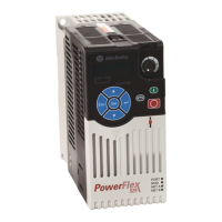
PowerFlex 525 Adjustable Frequency
AC Drive
Catalog Number 25B
Additional Resources
These documents contain additional information concerning the installation, programming, and
application of the AC drive.
Mounting Considerations
• Mount the drive upright on a flat, vertical and level surface.
• Protect the cooling fan by avoiding dust or metallic particles.
• Do not expose to a corrosive atmosphere.
• Protect from moisture and direct sunlight.
Minimum Mounting Clearances
Vertical mounting is shown. If mounting horizontally, apply same clearances plus 50 mm (2.0 in.)
clearance from the top and bottom of enclosure to allow for proper airflow.
(1) For Frame E with Fan Kit only, clearance of 95 mm (3.7 in.) is required.
(2) For Frame E with Fan Kit only, clearance of 12 mm (0.5 in.) is required.
Ambient Operating Temperatures
(1) IP 30/NEMA 1/UL Type 1 rating requires installation of the PowerFlex 520-Series IP 30/NEMA 1/UL Type 1 option kit,
catalog number 25-JBAx.
(2) For catalogs 25B-D1P4N104 and 25B-E0P9N104, the temperature listed under the Max. (Derate) column is reduced by 5
°C (9 °F) for all mounting methods.
(3) For catalogs 25B-D1P4N104 and 25B-E0P9N104, the temperature listed under the Max. with Fan Kit (Derate) column is
reduced by 10 °C (18 °F) for vertical and vertical with zero stacking mounting methods only.
(4) Catalogs 25B-D1P4N104 and 25B-E0P9N104 cannot be mounted using either of the horizontal mounting methods.
(5) Requires installation of the PowerFlex 520-Series Control Module Fan Kit, catalog number 25-FANx-70C.
Drive Dimensions
PowerFlex 525 Frames
Ratings are in kW and (HP).
IP20/Open Type
Dimensions are in mm and (in.). Weights are in kg and (lb).
EMC Filters
See the PowerFlex 525 User Manual for instructions on complying with the EMC Directive.
Dimensions are in mm and (in.).
Fuses and Circuit Breakers
Power Wiring
Recommended Shielded Wire
ATTENTION:
• Before installing, configuring, operating or maintaining this product, read
this document and the documents listed in the Additional Resources section
for installing, configuring, or operating equipment. Users should familiarize
themselves with installation and wiring instructions in addition to
requirements of all applicable codes, laws, and standards.
• Installation, adjustments, putting into service, use, assembly, disassembly, and
maintenance shall be carried out by suitably trained personnel in accordance with
applicable code of practice.
• If this equipment is used in a manner not specified by the manufacturer, the
protection provided by the equipment may be impaired.
• Solid state equipment has operational characteristics differing from those of
electromechanical equipment. Safety Guidelines for the Application, Installation
and Maintenance of Solid State Controls, publication SGI-1.1, available from your
local Rockwell Automation sales office or online at rok.auto/literature
describes
some important differences between solid state equipment and hard-wired
electromechanical devices.
ATTENTION: Do not install, configure, operate or maintain this product until you
have read the product documentation and the documents in the Additional
Resources section for installing, configuring, operating or maintaining equipment.
To get the product documentation go to rok.auto/literature
or contact your local
sales office or Rockwell Automation representative.
ATTENTION: Ne pas installer, configurer, exploiter ou maintenir ce produit tant que
vous n’avez pas lu sa documentation et les documents de la rubrique Documents
connexes pour l’installation, la configuration, l’exploitation et la maintenance de
l’équipement. Pour obtenir de la documentation, rendez-vous sur le site
rok.auto/literature
ou contactez votre agence commerciale Rockwell Automation
locale ou son représentant.
ACHTUNG: Für die Installation, Konfiguration, den Betrieb und die Wartung dieses
Produkt lesen Sie sich bitte zunächst die Produktdokumentation sowie die
Dokumente im Abschnitt “Weitere Informationen” durch. Die entsprechende
Produktdokumentation finden Sie unter rok.auto/literature
oder kontaktieren Sie Ihr
lokales Vertriebsbüro bzw. einen Rockwell Automation-Mitarbeiter.
ATENCIÓN: No instale, configure, opere ni mantenga este producto hasta que haya
leído la documentación del producto y los documentos en la sección Recursos
adicionales para la instalación, configuración, operación o mantenimiento de
equipo. Para conseguir la documentación, diríjase a rok.auto/literature o póngase
en contacto con su oficina regional de ventas o representante de Rockwell
Automation.
ATENÇÃO: Não instale, configure, opere ou mantenha este produto até que você leia
a documentação do produto e os documentos na seção Recursos adicionais para a
instalação, configuração, operação ou manutenção do equipamento. Para conseguir
a documentação, visite rok.auto/literature
ou entre em contato con seu escritório
de vendas regional ou representante da Rockwell Automation.
ATTENZIONE: Non installare, configurare, attivare o riparare questo prodotto senza
avere prima letto la relativa documentazione nonchè i documenti indicati nella
sezione Ulteriori Risore riguardanti l'installazione, la configurazione, l'attivazione o la
riparazione dell'apparecchiatura. Per la documentazione sul prodotto visitare il sito
rok.auto/literature
o contattare l'ufficio vendite o il rappresentate Rockwell
Automation di zona.
ВНИМАНИЕ: Не устанавливайте, не конфигурируйте, не запускайте в эксплуатацию и не
поддерживайте работу продукта до прочтения технической документации по продукту
и документации в разделе Дополнительные материалы для инсталлирования,
конфигурирования, запуска в эксплуатацию и поддержки работы продукта. Чтобы
ознакомиться с документацией по продукту, перейдите по ссылке rok.auto/literature
или свяжитесь с локальным офисом продаж или представителем Rockwell Automation.
UWAGA: Nie instaluj i nie uruchamiaj tego urządzenia dopóki nie zapoznasz się z
instrukcją użytkownika produktu. Aby uzyskać dokumentację produktu przejdź do
strony internetowej rok.auto/literature
lub skontaktuj się z lokalnym biurem
sprzedaży lub przedstawicielstwem firmy Rockwell Automation.
UPOZORŇENÍ: Neprovádějte instalaci, konfiguraci, provoz ani údržbu, pokud jste
dosud nepřečetli dokumentaci k produktu a dokumenty obsažené v sekci Doplňující
informace pro instalaci, konfiguraci, provoz a údržbu. Tuto dokumentaci můžete
získat na rok.auto/literature
nebo od obchodního zástupce společnosti Rockwell
Automation.
English The user manual is available in multiple languages at rok.auto/literature
. Select
publication language and type “520-UM001“ in the search field.
Deutsch Das benutzer handbuch steht in mehreren Sprachen unter rok.auto/literature
zur
Verfügung. Wählen Sie Ihre Sprache aus, und geben Sie „520-UM001“ in das Suchfeld
ein.
Français La manuel utilisateur est disponible dans différentes langues à l’adresse suivante:
rok.auto/literature
. Sélectionner la langue puis taper « 520-UM001 » dans le champ
de recherche.
Italiano La manuale d'uso è disponibile in varie lingue sul sito rok.auto/literature
.
Selezionare la lingua desiderata e digitare “520-UM001“ nel campo di ricerca.
Español Puede encontrar el manual del usuario en varios idiomas en rok.auto/literature
.
Selecione el idioma de publicación y escriba “520-UM001“ en el campo de búsqueda.
Português
O manual de usuário está disponível em várias línguas em rok.auto/literature.
Seleccione a língua de publicação e entre com “520-UM001“ no espaço de busca.
Русский Руководство пользователя на других языках можно найти по адресу
rok.auto/literature
. Выберите язык и введите в окно поиска «520-UM001».
Český Uživatelská příručka je k dispozici ve více jazykových verzích na adrese
rok.auto/literature
. Zvolte jazyk publikace a do vstupního pole pro vyhledávání
zadejte „520-UM001“.
Polski Instrukcja obsługi dostępna jest w wielu językach na stronie rok.auto/literature
.
Wybrać język publikacji, w polu wyszukiwania wpisać “520-UM001”.
PowerFlex® 520-Series Adjustable Frequency AC Drive User Manual, publication 520-UM001
:
Detailed information on the parameters and specifications of the PowerFlex 523 and PowerFlex
525 drives.
ὀព㸸ὀព㸸〇ရࡢ㈨ᩱ࠾ࡼࡧ㏣ຍ㈨ᩱグ㍕ࡢ⨨ࡢྲྀࡅࠊᵓᡂࠊ᧯సࠊ
ࡲࡓࡣಖᏲ㛵ࡍࡿ㈨ᩱࢆ࠾ㄞࡳ࡞ࡿࡲ࡛ࡣࠊࡇࡢ〇ရࡢྲྀࡅࠊ
ᵓᡂࠊ᧯సࠊࡲࡓࡣಖᏲࢆ⾜࡞ࢃ࡞࠸࡛ࡃࡔࡉ࠸ࠋ〇ရࡢ㈨ᩱࢆ
ධᡭࡍࡿࡣ ࠊ:HEࢧࢺ㸸rok.auto/literature ࢡࢭࢫࡍࡿࠊ
ࡲࡓࡣࣟࢵࢡ࢙࣭࣮࢘ࣝ࢜ࢺ࣓࣮ࢩࣙࣥࡢႠᴗࡲࡓࡣ
㈍௦⌮ᗑࡲ࡛ࡈ㐃⤡ࡃࡔࡉ࠸ࠋ
주의사항
:
제품 매뉴얼 혹은설치 , 구성 , 가동 , 유지와 관련된 추가 지침서를
완전히 숙지하기 전까지 본 제품을 설치 혹은 가동하 지 마십시오 . 본 제품과
관련된 매뉴얼 혹은 문서를 원하시면 사이트 rok.auto/literature 를 방문
해주시거나 해당 지역의 로크웰 오토메이션대리점으 로 문의하십시오 .
注意
若未阅读产品文档以及“ 其它资源” 小节中提及的有关安装、配置、
运行或维护设备的相关文档,请勿安装、配置、运行或维护本产品。请访问
rok.auto/literature 或联系您当地的销售办事处或罗克韦尔自动化代表,
以获取产品文档。
注意:注意:
在您完整閱讀本產品相關文件及其他關於安裝、 配置、 操作或
維護設備等資料之前、 請勿安裝、 配置、 操作或維護此產品。您可到下列
網站下載所有產品相關文件 rok.auto/literature ,或聯繫洛克威爾自動化當地
辦公室。
rok.auto/literature
.
"520-UM001" .
㌂㣿㧦 ⰺⓊ㠒
从以下网页可以获得用户手册的多种语言的版本: rok.auto/literature 。
请选择出版物的语言, 并在搜索栏输入“520-UM001” 印。
࣮ࣘࢨ࣮ࢬ࣐ࢽࣗࣝࡢከゝㄒ∧ࡣ:HEࢧࢺrok.auto/literatureࠉ
࡚ධᡭ࡛ࡁࡍࠋฟ∧ゝㄒࢆ㑅ᢥࡋࠊ᳨⣴ࣇ࣮ࣝࢻ
ࠕ80ࠖࢱࣉࡋ࡚ࡃࡔࡉ࠸ࠋ
以下網頁提供使用手册的多國語言版本:rok.auto/literature 。
請選擇出版語言,並於搜尋欄鍵入Ā80ā 即可。
AC Drive Installation Considerations, publication DRIVES-IN003: Provides additional information
needed to properly install PowerFlex AC drives.
Wiring and Grounding Guidelines for Pulse Width Modulated (PWM) AC Drives, publication
DRIVES-IN001
: Provides basic information needed to properly wire and ground PWM AC drives.
Industrial Automation Wiring and Grounding Guidelines, publication 1770-4.1
: Provides general
guidelines for installing a Rockwell Automation industrial system.
Frame Screw Size Screw Torque
A M5 (#10…24) 1.56…1.96 N•m (14…17 lb•in)
B M5 (#10…24) 1.56…1.96 N•m (14…17 lb•in)
C M5 (#10…24) 1.56…1.96 N•m (14…17 lb•in)
D M5 (#10…24) 2.45…2.94 N•m (22…26 lb•in)
E M8 (5/16 in.) 6.0…7.4 N•m (53…65 lb•in)
Mounting Enclosure Rating
(1)
Ambient Temperature
Min. Max.
(No Derate)
Max.
(Derate)
(2)
Max. with
Fan Kit
(Derate)
(3)(5)
Vertical IP 20/Open Type
-20 °C (-4
°F)
50 °C (122 °F) 60 °C (140
°F)
70 °C (158 °F)
IP 30/NEMA 1/UL Type 1 45 °C (113 °F) 55 °C (131 °F) –
Vertical, Zero Stacking IP 20/Open Type 45 °C (113 °F) 55 °C (131 °F) 65 °C (149 °F)
IP 30/NEMA 1/UL Type 1 40 °C (104 °F) 50 °C (122
°F)
–
Horizontal with
Control Module Fan Kit
(4)(5)
IP 20/Open Type 50 °C (122 °F) – 70 °C (158 °F)
Horizontal, Zero Stacking
with
Control Module Fan Kit
(4)(5)
IP 20/Open Type 45 °C (113 °F) – 65 °C (149 °F)
Frame 1-Phase
100...120V
1-Phase
200...240V
1-Phase
200...240V
w/ Filter
3-Phase
200...240V
3-Phase
380...480V
3-Phase
380...480V
w/ Filter
3-Phase
525...600V
A0.4
(0.5)
0.4...0.75
(0.5...1.0)
0.4...0.75
(0.5...1.0)
0.4...2.2
(0.5...3.0)
0.4...2.2
(0.5...3.0)
0.4...2.2
(0.5...3.0)
0.4...2.2
(0.5...3.0)
B 0.75...1.1
(1.0...1.5)
1.5...2.2
(2.0...3.0)
1.5...2.2
(2.0...3.0)
3.7
(5.0)
4.0
(5.0)
4.0
(5.0)
3.70
(5.00)
C– – – 5.5
(7.5)
5.5...7.5
(7.5...10.0)
5.5...7.5
(7.5...10.0)
5.5...7.5
(7.5...10.0)
D– – – 7.5
(10.0)
11.0...15.0
(15.0...20.0)
11.0...15.0
(15.0...20.0)
11.0...15.0
(15.0...20.0)
E – – – 11.0...15.0
(15.0...20.0)
– 18.5...22.0
(25.0...30.0)
18.5...22.0
(25.0...30.0)
Frame A B C D E Ship Weight
A 72 (2.83) 152 (5.98) 172 (6.77) 57.5 (2.26) 140 (5.51) 1.1 (2.4)
B 87 (3.43) 180 (7.09) 172 (6.77) 72.5 (2.85) 168 (6.61) 1.6 (3.5)
C 109 (4.29) 220 (8.66) 184 (7.24) 90.5 (3.56) 207 (8.15) 2.3 (5.0)
D 130 (5.12) 260 (10.24) 212 (8.35) 116 (4.57) 247 (9.72) 3.9 (8.6)
E 185 (7.28) 300 (11.81) 279 (10.98) 160 (6.30) 280 (11.02) 12.9 (28.4)
50 mm
(2.0 in.)
50 mm
(2.0 in.)
50 mm
(2.0 in.)
50 mm
(2.0 in.)
50 mm
(2.0 in.)
50 mm
(2.0 in.)
(1)
(2)
50 mm
(2.0 in.)
25 mm
(1.0 in.)
25 mm
(1.0 in.)
50 mm
(2.0 in.)
(1)
Vertical Vertical, Zero Stacking
No clearance required between drives.
Vertical, Zero Stacking with Fan Kit
No clearance required between drives.
Vertical with Fan Kit
Catalog No.
(1)
(1)
Normal and Heavy duty ratings are available for this drive.
Output Ratings Input Ratings Branch Circuit Protection
IP20/Open Type
Watts Loss
Normal
Duty
Heavy
Duty
Amps
Voltage
Range
kVA
Max Amps
(2)
(2)
When the drive is controlling motors with lower amp ratings, refer to the drive nameplate for drive input current
rating.
Fuse Ratings
Min./Max.
140M Motor
Protectors
(3)
(4)
(5)
(3)
The AIC ratings of the Bulletin 140M Motor Protector Circuit Breakers may vary. See Bulletin 140M Motor Protection
Circuit Breakers Application Ratings.
(4)
Bulletin 140M with adjustable current range should have the current trip set to the minimum range that the device will
not trip.
(5)
Manual Self-Protected (Type E) Combination Motor Controller, UL listed for 208 Wye or Delta, 240 Wye or Delta,
480Y/277 or 600Y/347. Not UL listed for use on 480V or 600V Delta/Delta, corner ground, or high-resistance ground
systems.
Contactors
HP kW HP kW
100...120V AC (-15%, +10%) – 1-Phase Input, 0...230V 3-Phase Output
25B-V2P5N104 0.5 0.4 0.5 0.4 2.5 85...132 1.3 9.6 16/20 140M-C2E-C10 100-C12 27.0
25B-V4P8N104 1.0 0.75 1.0 0.75 4.8 85...132 2.5 19.2 25/40 140M-D8E-C20 100-C23 53.0
25B-V6P0N104 1.5 1.1 1.5 1.1 6.0 85...132 3.2 24.0 32/50 140M-F8E-C25 100-C23 67.0
200...240V AC (-15%, +10%) – 1-Phase Input, 0...230V 3-Phase Output
25B-A2P5N104 0.5 0.4 0.5 0.4 2.5 170...264 1.7 6.5 10/16 140M-C2E-C10 100-C09 29.0
25B-A4P8N104 1.0 0.75 1.0 0.75 4.8 170...264 2.8 10.7 16/25 140M-C2E-C16 100-C12 50.0
25B-A8P0N104 2.0 1.5 2.0 1.5 8.0 170...264 4.8 18.0 25/40 140M-F8E-C25 100-C23 81.0
25B-A011N104 3.0 2.2 3.0 2.2 11.0 170...264 6.0 22.9 32/50 140M-F8E-C25 100-C37 111.0
200...240V AC (-15%, +10%) – 1-Phase Input with EMC Filter, 0...230V 3-Phase Output
25B-A2P5N114 0.5 0.4 0.5 0.4 2.5 170...264 1.7 6.5 10/16 140M-C2E-C10 100-C09 29.0
25B-A4P8N114 1.0 0.75 1.0 0.75 4.8 170...264 2.8 10.7 16/25 140M-C2E-C16 100-C12 53.0
25B-A8P0N114 2.0 1.5 2.0 1.5 8.0 170...264 4.8 18.0 25/40 140M-F8E-C25 100-C23 84.0
25B-A011N114 3.0 2.2 3.0 2.2 11.0 170...264 6.0 22.9 32/50 140M-F8E-C25 100-C37 116.0
200...240V AC (-15%, +10%) – 3-Phase Input, 0...230V 3-Phase Output
25B-B2P5N104 0.5 0.4 0.5 0.4 2.5 170...264 1.2 2.7 6/6 140M-C2E-B40 100-C09 29.0
25B-B5P0N104 1.0 0.75 1.0 0.75 5.0 170...264 2.7 5.8 10/16 140M-C2E-B63 100-C09 50.0
25B-B8P0N104 2.0 1.5 2.0 1.5 8.0 170...264 4.3 9.5 16/20 140M-C2E-C10 100-C12 79.0
25B-B011N104 3.0 2.2 3.0 2.2 11.0 170...264 6.3 13.8 20/32 140M-C2E-C16 100-C23 107.0
25B-B017N104 5.0 3.7 5.0 3.7 17.5 170...264 9.6 21.1 32/45 140M-F8E-C25 100-C23 148.0
25B-B024N104 7.5 5.5 7.5 5.5 24.0 170...264 12.2 26.6 35/63 140M-F8E-C32 100-C37 259.0
25B-B032N104 10.0 7.5 10.0 7.5 32.2 170...264 15.9 34.8 45/70 140M-F8E-C45 100-C43 323.0
25B-B048N104 15.0 11.0 15.0 11.0 48.3 170...264 20.1 44.0 63/90 140M-F8E-C45 100-C60 584.0
25B-B062N104 20.0 15.0 15.0 11.0 62.1 170...264 25.6 56.0 70/125 – 100-C72 708.0
380...480V AC (-15%, +10%) – 3-Phase Input, 0...460V 3-Phase Output
25B-D1P4N104 0.5 0.4 0.5 0.4 1.4 323...528 1.7 1.9 3/6 140M-C2E-B25 100-C09 27.0
25B-D2P3N104 1.0 0.75 1.0 0.75 2.3 323...528 2.9 3.2 6/10 140M-C2E-B40 100-C09 37.0
25B-D4P0N104 2.0 1.5 2.0 1.5 4.0 323...528 5.2 5.7 10/16 140M-C2E-B63 100-C09 80.0
25B-D6P0N104 3.0 2.2 3.0 2.2 6.0 323...528 6.9 7.5 10/16 140M-C2E-C10 100-C09 86.0
25B-D010N104 5.0 4.0 5.0 4.0 10.5 323...528 12.6 13.8 20/32 140M-D8E-C16 100-C23 129.0
25B-D013N104 7.5 5.5 7.5 5.5 13.0 323...528 14.1 15.4 20/35 140M-D8E-C20 100-C23 170.0
25B-D017N104 10.0 7.5 10.0 7.5 17.0 323...528 16.8 18.4 25/40 140M-D8E-C20 100-C23 221.0
25B-D024N104 15.0 11.0 15.0 11.0 24.0 323...528 24.1 26.4 35/63 140M-F8E-C32 100-C37 303.0
25B-D030N104 20.0 15.0 15.0 11.0 30.0 323...528 30.2 33.0 45/70 140M-F8E-C45 100-C43 387.0
380...480V AC (-15%, +10%) – 3-Phase Input with EMC Filter, 0...460V 3-Phase Output
25B-D1P4N114 0.5 0.4 0.5 0.4 1.4 323...528 1.7 1.9 3/6 140M-C2E-B25 100-C09 27.0
25B-D2P3N114 1.0 0.75 1.0 0.75 2.3 323...528 2.9 3.2 6/10 140M-C2E-B40 100-C09 37.0
25B-D4P0N114 2.0 1.5 2.0 1.5 4.0 323...528 5.2 5.7 10/16 140M-C2E-B63 100-C09 81.0
25B-D6P0N114 3.0 2.2 3.0 2.2 6.0 323...528 6.9 7.5 10/16 140M-C2E-C10 100-C09 88.0
25B-D010N114 5.0 4.0 5.0 4.0 10.5 323...528 12.6 13.8 20/32 140M-D8E-C16 100-C23 133.0
25B-D013N114 7.5 5.5 7.5 5.5 13.0 323...528 14.1 15.4 20/35 140M-D8E-C20 100-C23 175.0
25B-D017N114 10.0 7.5 10.0 7.5 17.0 323...528 16.8 18.4 25/40 140M-D8E-C20 100-C23 230.0
25B-D024N114 15.0 11.0 15.0 11.0 24.0 323...528 24.1 26.4 35/63 140M-F8E-C32 100-C37 313.0
25B-D030N114 20.0 15.0 15.0 11.0 30.0 323...528 30.2 33.0 45/70 140M-F8E-C45 100-C43 402.0
25B-D037N114 25.0 18.5 20.0 15.0 37.0 323...528 30.8 33.7 45/70 140M-F8E-C45 100-C43 602.0
25B-D043N114 30.0 22.0 25.0 18.5 43.0 323...528 35.6 38.9 50/80 140M-F8E-C45 100-C60 697.0
525...600V AC (-15%, +10%) – 3-Phase Input, 0...575V 3-Phase Output
25B-E0P9N104 0.5 0.4 0.5 0.4 0.9 446...660 1.4 1.2 3/6 140M-C2E-B25 100-C09 22.0
25B-E1P7N104 1.0 0.75 1.0 0.75 1.7 446...660 2.6 2.3 3/6 140M-C2E-B25 100-C09 32.0
25B-E3P0N104 2.0 1.5 2.0 1.5 3.0 446...660 4.3 3.8 6/10 140M-C2E-B40 100-C09 50.0
25B-E4P2N104 3.0 2.2 3.0 2.2 4.2 446...660 6.1 5.3 10/16 140M-C2E-B63 100-C09 65.0
25B-E6P6N104 5.0 3.7 5.0 3.7 6.6 446...660 9.1 8.0 10/20 140M-C2E-C10 100-C09 95.0
25B-E9P9N104 7.5 5.5 7.5 5.5 9.9 446...660 12.8 11.2 16/25 140M-C2E-C16 100-C16 138.0
25B-E012N104 10.0 7.5 10.0 7.5 12.0 446...660 15.4 13.5 20/32 140M-C2E-C16 100-C23 164.0
25B-E019N104 15.0 11.0 15.0 11.0 19.0 446...660 27.4 24.0 32/50 140M-F8E-C25 100-C30 290.0
25B-E022N104 20.0 15.0 15.0 11.0 22.0 446...660 31.2 27.3 35/63 140M-F8E-C32 100-C30 336.0
25B-E027N104 25.0 18.5 20.0 15.0 27.0 446...660 28.2 24.7 35/50 140M-F8E-C32 100-C30 466.0
25B-E032N104 30.0 22.0 25.0 18.5 32.0 446...660 33.4 29.2 40/63 140M-F8E-C32 100-C37 562.0
Location Rating/Type
Standard (Option 1) 600V, 90 °C (194 °F) XHHW2/RHW-2
Anixter B209500-B209507, Belden 29501-29507, or equivalent
Standard (Option 2) Tray rated 600V, 90 °C (194 °F)
RHH/RHW-2 Anixter OLF-7xxxxx or equivalent
Class I & II; Division I & II Tray rated 600V, 90 °C (194 °F)
RHH/RHW-2 Anixter 7V-7xxxx-3G or equivalent
Frame
ABCDEFGHI
A55.0
(2.17)
72.0
(2.83)
234.0
(9.21)
30.0
(1.18)
223.0
(8.78)
54.0
(2.13)
20.0
(0.79)
23.0
(0.91)
5.5
(0.22)
B70.0
(2.76)
87.0
(3.43)
270.0
(10.63)
35.0
(1.38)
258.0
(10.16)
58.0
(2.28)
25.0
(0.98)
24.0
(0.94)
5.5
(0.22)
C70.0
(2.76)
109.0
(4.29)
275.0
(10.83)
37.0
(1.46)
263.0
(10.35)
76.0
(2.99)
25.0
(0.98)
28.0
(1.10)
5.5
(0.22)
D80.0
(3.15)
130.0
(5.12)
310.0
(12.20)
33.0
(1.30)
298.0
(11.73)
90.0
(3.54)
33.0
(1.30)
28.0
(1.10)
5.5
(0.22)
E80.0
(3.15)
155.0
(6.10)
390.0
(15.35)
32.0
(1.26)
375.0
(14.76)
110.0
(4.33)
33.0
(1.30)
28.0
(1.10)
5.5
(0.22)