Rockwell Automation Publication 750-UM002H-EN-P - February 2017 21
Installation and Wiring Chapter 2
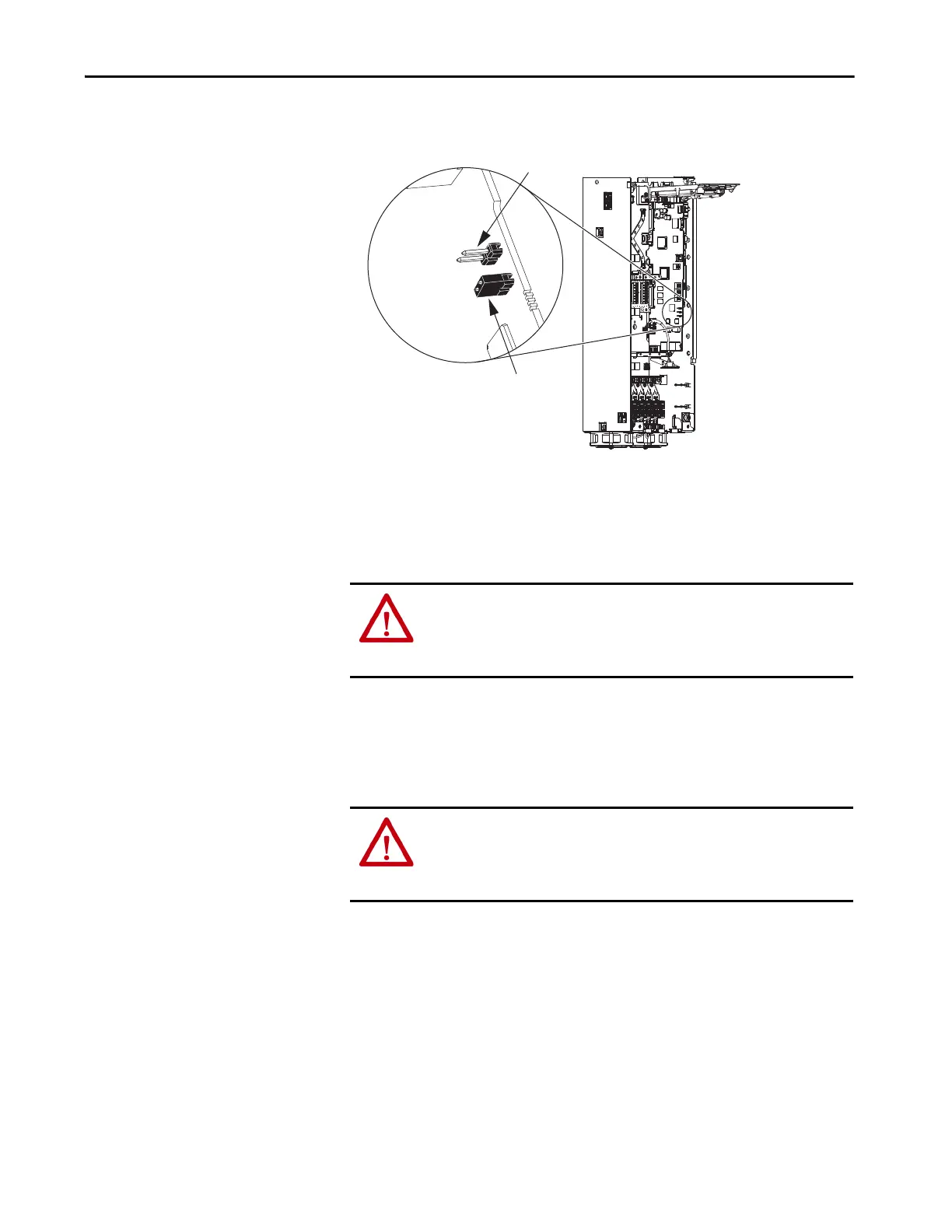
Figure 4 - PowerFlex 755T Drive Products Jumper Locations
Remove Power From the
Drive System
Before installation, remove power from the drive system and verify that the
voltage on the bus capacitors has discharged before performing any work on
the drive. The voltage at all test points must be 0 volts.
1. Turn off and lockout all input power, including any external power
sources (such as an Active Front End or other DC power source).
2. If present, turn off and lockout any external, single-phase 120/240V
power source.
Verify Zero Voltage on PowerFlex 755 and PowerFlex 753 Drives
For PowerFlex 755 and PowerFlex 753 Drives (Frames 1…7), measure the
DC-bus voltage at the Power Terminal Block by measuring between the:
•+DC and -DC terminals
• +DC terminal and the chassis
• -DC terminal and the chassis.
PowerFlex 755TL,
PowerFlex 755TR, and
PowerFlex 755TM Control Pod
SAFETY Enable
(jumper removed)
Hardware ENABLE
(jumper in place)
ATTENTION: To avoid an electric shock hazard when servicing the drive, a
means for Lockout/Tagout of the external, single-phase 120/240V power
source and, if present, external 120V uninterruptible power supply source,
must be provided.
ATTENTION: Hazard of equipment damage exists if a safety option module
is installed or removed while the drive is powered. To avoid damaging the
drive, verify that the voltage on the bus capacitors has discharged before
performing any work on the drive.
 Loading...


