Target/Actuator
1
Target/Actuator
2
Target/Actuator
3
Target/Actuator
4
Target/Actuator
5
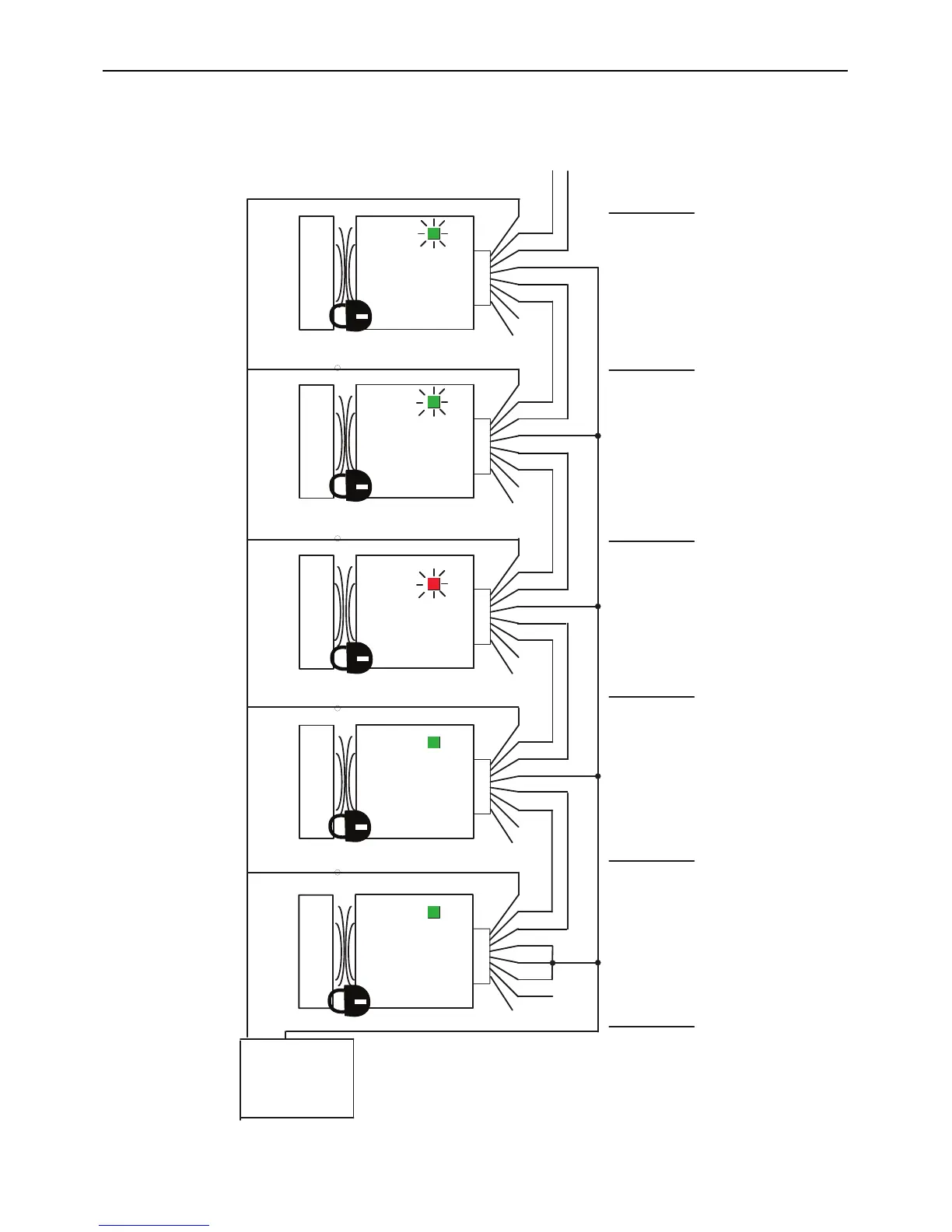
Switch 1 Switch 2 Switch 3 Switch 4 Switch 5
RTN
24V DC
Power
Supply
+24
1606-
XL120D
Green
Blue
Pink
Grey
Brown
Red
Yellow
White
+24V
+24V
Green
Blue
Pink
Grey
Brown
Red
Yellow
White
+24V
+24V
Green
Blue
Pink
Grey
Brown
Red
Yellow
White
+0V
+0V
Green
Blue
Pink
Grey
Brown
Red
Yellow
White
+0V
+0V
Green
Blue
Pink
Grey
Brown
Red
Yellow
White
+0V
+0V
Recoverable
fault
Actuator 1 is in sensing range
and locked.
Switch 1 is funtioning properly.
OSSDs are energized to 24V.
Green LED is ON.
Actuator 2 is in sensing range
and locked.
Switch 2 is funtioning properly.
OSSDs are energized to 24V.
Green LED is ON.
Actuator 3 is in sensing range
and locked.
Switch 3 has a fault.
See Diagnostic table.
Red LED is ashing.
Actuator 4 is in sensing range
and locked.
Switch 4 is functioning properly
Series inputs are 0V.
OSSDs are de-energized to 0V.
Green LED is ashing to indicate
series inputs are not 24V.
Actuator 5 is in sensing range
and locked.
Switch 5 is functioning properly
Series inputs are 0V.
OSSDs are de-energized to 0V.
Green LED is ashing to indicate
series inputs are not 24V.
OSSDs
are OFF
 Loading...