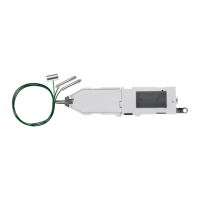
Roco-Under-baseboard-Motor for Turnouts in Gauges H0, H0e, and N.
Technical Data
Operating voltage 14-16V
Switching current 0,6A
Contact load max. 1A
The ROCO under-baseboard motor is equipped with two electromagnetic coils with end-of-stroke power dis-
connect. The reliable operation of the power disconnect facilitates a low current draw and assures a positive
activation of the turnout. Additionally, the under-baseboard motor incorporates a relay with 4 independent
switching contacts. This makes it possible to perform other functions (e.g. polarisation of turnout frog, switching
power supply) while operating the turnout. An illuminated turnout lantern (40293) may be added as well.
Installation:
1. Mounting hole
A hole with 10 mm diameter must be drilled in the baseboard prior to mounting the motor. The turnout must
be placed in exact position on the baseboard before the drill centre is marked. A marker point is made on the
baseboard through the activator wire hole in the throw bar (1) in both right - and left hand position of the
turnout (fig. 1). After removal of the turnout, the centre of the hole to be drilled is marked halfway between
the two marker points, if necessary, the drilling may be expedited by using a centre punch first. It is advisable
to drill a smaller hole (2.5 - 3 mm) before drilling the 10 mm hole.
Please note:
For reliable operation of the under-baseboard motor a board thickness between 14-16 mm (5/8“) should
be used. When using thinner baseboards, a suitably sized (80 x 55 cm) plywood space should be used to
adjust to the required thickness (fig. 4).
2. Mounting the under-baseboard motor
Before final installation of the motor, the activator wire guide (3) must be fitted to the thickness of the baseboard.
When mounting several motors, it is useful to prepare a cutting template. A board remnant having the same
entsprechend abgestimmt auf alle elektrischen Anlagen-teile garantiert dies einen sicheren und sauberen
Aufbau.
In Fig. 10 ist der Anschluss an einen ROCO Weichenschalter 10520 und das Anschlussschema zur Polari-
sierung eines Weichenherzstückes dargestellt. Der Betriebs-Anschluss kann nur über die mittlere Steckerzone
erfolgen.
Im Normaleinbau benötigt der Unterflurantrieb eine lichte Höhe von mindestens 55 mm. Im Bedarfsfall
kann der Unterflurantrieb auch liegend eingebaut werden, wodurch eine Einbauhöhe von nur 32 mm
erreicht wird.
Zur liegenden Montage muss der Antrieb umgerüstet werden. Die dazu erforderlichen Umrüstteile liegen
der Packung bei.
1. Die Stelldrahtführung (3) und den Stellhebel (4) entfernen
2. Den Halterahmen (5) aufspreizen und nach unten abziehen (Fig. 5).
3. Den abgewinkelten Montagerahmen (9) soweit aufschieben, bis dieser am Anschlag einrastet (Fig. 6).
4. Den Stelldraht (10) in den Stellhebel (11) einlegen und mit der Kappe (12) fixieren (Fig. 7).
5. Stellhebel einsetzen - der Zapfen des Stellhebels muss dabei in den Mitnehmerschlitz des Antriebes
gelangen (Fig. 8).
6. Die Abdeckung (13) aufdrücken - anschließend kann der Unterflurantrieb über die Schraubenlaschen
montiert werden (Fig. 9).
Wird der Unterflurantrieb liegend eingebaut, ist eine Verwendung der Weichenlaterne nicht möglich.
 Loading...