15
GB
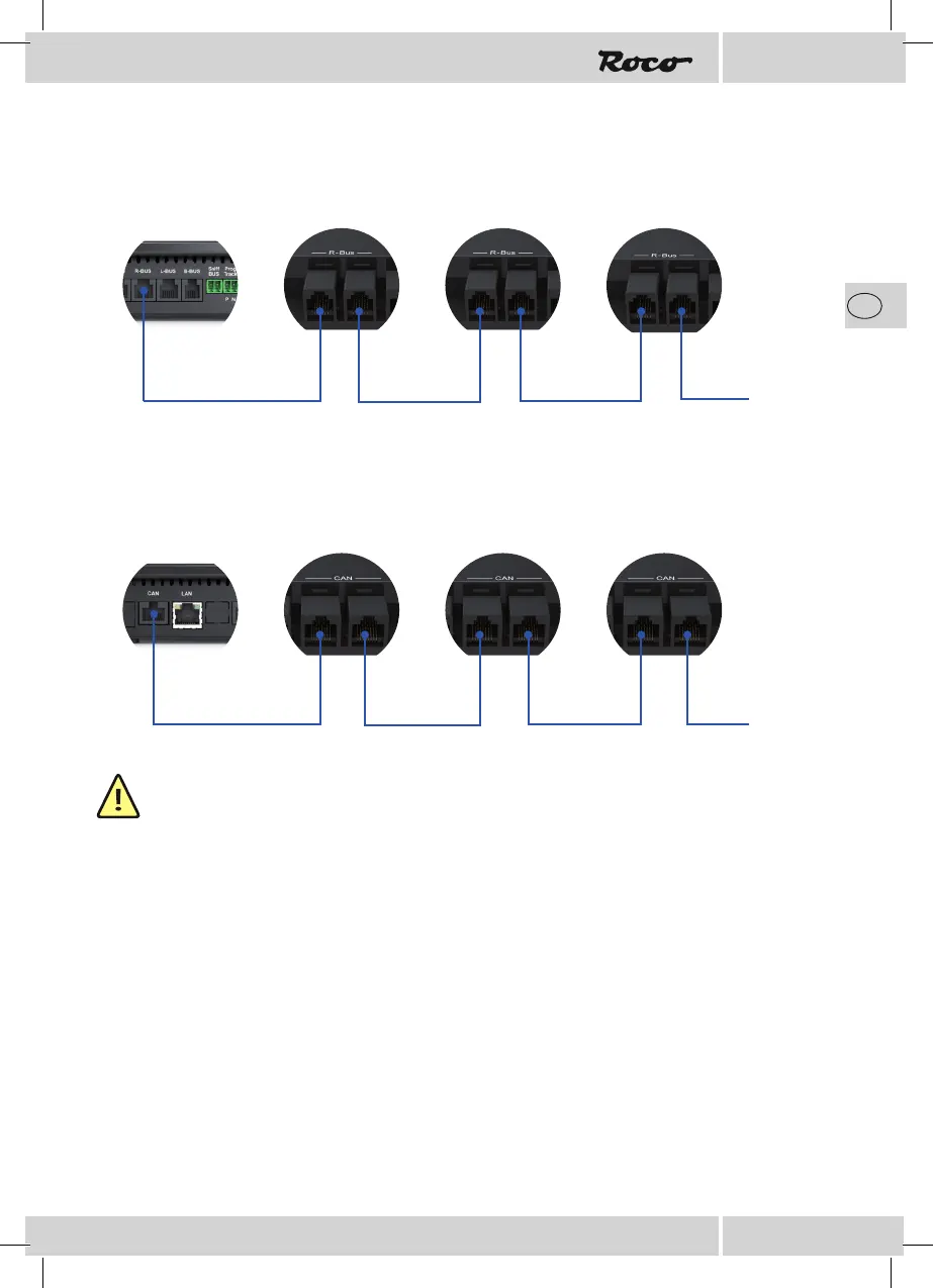
Connection via R-BUS
Connection via CAN-BUS
NOTE: Please note that only the enclosed connecting cables are to be used as these have a suf -
ciently large cross-section that ensure an optimal current supply.
Confi guration
Confi guration using push-buttons
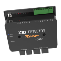
Connect the Z21 detector to your chosen bus system and provide the track inputs P and N on the Z21
detector with the track voltage from the control centre.
The blue status LED ashes brie y and only remains illuminated when it is connected to the CAN or the
R-BUS respectively.
Press the programming button on the Z21 detector for at least 1 second; the white program LED starts to
ash.
Activate a magnet article with the address of your choice within the next minute.
The magnet article can be activated using the Z21 App or another input device such as the MULTIMAUS.
The address has been accepted by the Z21 detector after the white program LED has stopped ashing.
Z21 Z21 Detector Z21 Detector Z21 Detector
etc.
Z21 Z21 Detector Z21 Detector Z21 Detector
etc.