Do you have a question about the Rodix 121-000-0893 and is the answer not in the manual?
Match the control's pulse mode to the feeder's tuning for 60 or 120 pulse output.
Adjust the MAX output trimpot to limit the maximum vibration level of the feeder.
Adjust the MIN trimpot to just below the slowest speed for proper feed rate.
Controls output power with a logarithmic-tapered curve for fine control over speed.
Adjust the trimpot to ramp up output gradually, reducing part drops and shock.
Configure remote operation using a low current switch or hopper interlock.
Vary output remotely using 4-20mA signal from PLC or 0-5VDC analog input.
Feature adjusts output to compensate for supply voltage fluctuations.
Enable features like linear pot taper, 0-20mA control, and empty bowl timer.
Indicates active inputs and RUN status. LEDs turn ON when conditions are met.
Guidance for control operation issues like no run or humming.
Provides physical dimensions of the Feeder Cube control unit.
Describes symptoms like brief pauses or bumps in feeder output due to noise.
Identifies noise sources such as relay coils, contactors, and motors.
Provides guidelines for preventing electrical noise interference.
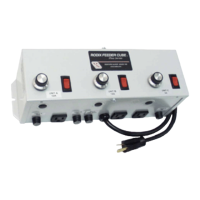
The Rodix Feeder Cube® FC-40 Plus Series is a general-purpose control device designed to manage vibratory feeders. This manual provides detailed instructions for its adjustments, setup, and troubleshooting, ensuring optimal performance and longevity.
The FC-40 Plus Series control regulates the output power to vibratory feeders, allowing for precise control over their vibration levels and feed rates. It features a main control dial for primary output adjustment and various trimpots for fine-tuning specific operational parameters. The device is designed to operate with different pulse settings (60, 120, 40, 30, or 60 Reverse pulse), which can be selected via DIP switches on the circuit card to match the feeder's tuning.
A key function is the ability to limit the maximum output of the control, preventing excessive vibration and potential damage to the feeder or parts. This is achieved through the MAX output trimpot, which can be adjusted to set the desired maximum vibration level when the main control dial is fully turned up. Similarly, a MIN trimpot allows for setting the minimum output level, ensuring a consistent feed rate even when the feeder is nearly empty. This trimpot also supports a "low speed" setting for 2-speed operation.
The main control dial provides a logarithmic-tapered power output curve, which is non-linear. This design spreads the power broadly across the dial, offering maximum "fine control" over the feeder's output speed. For applications requiring very precise adjustment at low amplitudes, the MIN trimpot can be increased, or the MAX trimpot decreased. A linear POT taper option is also available for the main control dial, which can be selected via the S1 Programming Chart.
Another important feature is the soft-start function, which allows the control output to ramp up to the desired level gradually instead of abruptly. This helps prevent parts from falling off tooling, reduces spring shock, and minimizes hammering when the control turns on. The soft-start rate can be adjusted from a gentle 6-second ramp-up to full output to no soft start at all.
The FC-40 Plus Series also supports remote OFF/ON control, which can be configured in several ways. A low current switch, such as a paddle switch, can replace the factory-installed Run Jumper. Alternatively, a feeder bowl/hopper interlock allows the hopper control to operate only when the bowl is running and a paddle switch contact is closed. This interlock input is controlled by the interlock output of a "Parts Sensing Feeder Bowl Control" like an FC-90 Plus. Furthermore, low voltage DC signals from a PLC or FC-90 Plus can be used to turn the control ON and OFF, with the input being optically isolated.
Remote speed control is also possible, allowing the output power level to be varied using external signals. A 4-20mA signal from a PLC can remotely control the output, overriding the main control dial. This input is transformer isolated from the power line, and shielded cables are recommended in noisy environments. A 0-5VDC analog input signal can also be used in place of the main control dial, with this input also being transformer isolated.
Line voltage compensation is a built-in feature that adjusts the control's output to counteract fluctuations in the supply voltage, thereby maintaining a consistent feed rate. This feature can be disabled if necessary.
The FC-40 Plus Series is designed for ease of use and flexibility in various industrial settings. Its modular design, with units A, B, and C, allows for different amperage configurations (10A, 15A, 5A respectively) to suit specific feeder requirements.
The device incorporates status LEDs that illuminate when any input is active and when the RUN input conditions are met, providing visual feedback on the control's operational status.
Supplementary software features can be enabled on the circuit boards, including linear pot taper, 0-20mA control, empty bowl timer, low pulse rates, and two-speed pots, further enhancing its adaptability.
For optimal performance and to avoid electrical noise problems, good wiring practices are crucial. Shielded wires should be used for all I/O signals, with the shield "drain" wire tied to the chassis in the Rodix control. I/O wires should be routed away from noisy equipment like relays, solenoids, and transformers. When using relays or solenoid valves, installing a Snubber (diode for DC coils, RC Snubber for AC coils) is recommended to reduce electrical noise. In extremely high EMI environments, power line filters and ferrite beads can be effective on I/O signal wires.
The FC-40 Plus Series is built for durability, but certain maintenance aspects are important for its longevity. Fuses should be replaced with specific "Fast Acting" types (Bussman ABC or Littelfuse 3AB) or equivalents of the manufacturer's original value to ensure proper protection.
The device comes with a two-year warranty covering defects in material and workmanship under normal use. For warranty service or repairs, the control should be shipped prepaid to Rodix Inc.'s Repair Department. If under warranty, repairs or replacements are free of charge; otherwise, charges for time, material, and return freight apply. Quotes for repairs are available upon request, and including a brief note describing the symptoms helps technicians address issues more efficiently.
It is important to note that mounting the control on a vibrating surface will void the warranty, emphasizing the need for a stable installation environment.
Troubleshooting guidance is provided to address common issues. For the control to run, the main control dial must be turned up, or the 4-20mA input must have over 4mA. The DIRECT LED must be lit, or both the INTERLOCK and EXT VOLTS LEDs must be on, depending on the configuration. If the feeder only hums, flipping the 60/120 dip switch is a recommended step.
| Part Number | 121-000-0893 |
|---|---|
| Category | Controller |
| Input Voltage | 24 VDC |
| Protection Class | IP20 |
| Dimensions | 30 mm |