EasyManua.ls Logo

Rodix FC-200 Plus Series - User Manual

Rodix FC-200 Plus Series
2 pages
Print Icon
To Next Page IconTo Next Page
Loading...
FC-200 & CFR-90
Plus
Series
Control with Constant Feed Rate
Option
Fig. 2 The arrow shows the direction of vibration
which is at a right angle to the spring pack.
Warning: Avoid dropping the sensor before
installation. Dropping the sensor on a hard
surface could damage it and void the warranty.
© 2000, 2019 RODIX INC.
1. GENERAL DESCRIPTION
Vibratory feeders are inherently unstable and are
very susceptible to changes in part load and power
line voltage fluctuations. These changes can
cause part jams or very few parts to be fed to the
machine. The Constant Feed Rate feature
corrects for fluctuations in the vibratory feeder
speed by using a sensor attached to the feeder to
monitor the vibration level. The control then keeps
the vibratory feeder operating with a constant
amount of vibration and thus a constant part feed
rate.
When something has caused a large change in
vibration, an approximate feed rate is restored
almost immediately. Then, the preferred feed rate
can be fully restored within a couple seconds.
Small changes in vibration are usually corrected
without the operator even knowing that a change
has occurred.
The sensor design incorporates a 4-20mA style of
output to provide immunity to electrical noise.
2. INSTALLING THE SENSOR
Note: Failure to adequately prepare the
feeder’s surface properly may result in a
sensor that will not bond to the feeder. The
sensor will not be mounted until step C-6.
A. ORIENT THE SENSOR so that its sensitive
axis is in the same direction as the vibration of the
feeder. The double-ended arrow in figure 1 shows
the sensor’s sensitive axis. Align the sensitive axis
of the sensor in the same direction as the vibration
(see figure 2). The sensor must be oriented
correctly for proper operation.
B. CHOOSE A LOCATION for mounting the
sensor on the feeder that is smooth and that will
allow the adhesive on the sensor to bond. Avoid
mounting the sensor over ridges and bumps which
can reduce the ability of the adhesive to stick to
the feeder. The correct location will also have
enough space for the sensor’s cable to hang
straight down without touching anything else.
C. SURFACE PREPARATION of the feeder is
crucial for proper bonding between the sensor and
the feeder. Please follow these steps completely.
1) The feeder should be kept between 70 and
100 F for ideal tape application.
2) Clean a three and one-half inch circular area
with a solvent like isopropyl alcohol that will not
leave a residue. As a rule of thumb, the area
can be considered clean when after cleaning the
area with a solvent-saturated, white paper-towel,
the towel is as clean as it was before wiping.
3) Using a good amount of pressure, polish the
cleaned, circular area of the feeder using a
scratch pad or steel wool. Repeat step 2, and
then go to step 4.
4) Wipe the cleaned surface with an alcohol wipe
or with a 50/50 isopropyl alcohol/water
combination.
5) Air dry or dry the surface thoroughly using a low
lint cloth or a clean paper towel.
6) Remove the vibration sensor from its protective
packaging. Remove the liner from the adhesive
backing. Avoid touching the tape. Apply the
vibration sensor to the prepared area of the
feeder. Press the sensor very firmly onto the
feeder surface for at least 10 seconds.
7) Allow the vibration sensor at least 20 minutes to
cure before operation. Note: It takes 72 hours
for the adhesive to fully cure at 70 F.
Alternatively, #8 or M4 screws can be used to
mount the sensor to the feeder. The hole centers
are 1.375” apart.
D. ROUTE THE SENSOR CABLE to protect it
from strain due to vibration. The cable that
attaches to the sensor will not break from normal
vibration; however, some care should be used
when routing the wire from the sensor to the
control.
123-170 CFR 1-17-2019.doc 1/17/2019
RODIX INC.
FEEDER CUBE
FC-200 & CFR-90
Plus
OPTION P/N 123-170
INSTALLATION AND
OPERATION
P/N 123-170
Fig. 1
Actual Size
1.375
Sensitive
Axis of
Vibration
Question and Answer IconNeed help?

Do you have a question about the Rodix FC-200 Plus Series and is the answer not in the manual?

Summary

General Description of Constant Feed Rate Control

Sensor Installation Procedures

Orient the Sensor

Align the sensor's sensitive axis with the feeder's vibration direction for proper operation.

Choose Sensor Mounting Location

Select a smooth feeder surface, avoiding ridges, with adequate space for the sensor's cable.

Prepare Sensor Mounting Surface

Clean, polish, and dry the mounting area using specified solvents for optimal adhesive bonding.

Route Sensor Cable

Route the sensor cable to protect it from strain due to vibration and prevent damage.

Control Configuration and Operation

Connect Sensor to Control

Connect the sensor's brown wire to +12VDC (TB2-9) and the blue wire to signal input (TB2-12).

Limit Maximum Output of CFR-90 Control

Adjust the MAX Output trimpot to prevent feeder hammering when at full power.

Control Operation

Turn the control ON and adjust the main dial for desired feed rate; it will self-regulate.

CFR-90 Main Control Dial Adjustment

Feedback adjusts output; recalibrate dial after changes for accurate setting representation.

Limit Maximum Power of FC-200 Control

Adjust the maximum power setting (40.0% to 100.0%) via the 'Power Settings' menu.

Application Tips and Warnings

Monitor vibration levels, handle sensor with care, and understand sound changes indicate regulation.

Overview

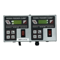
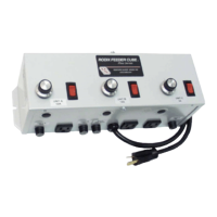
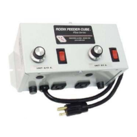
The Rodix Feeder Cube® FC-200 & CFR-90 Plus with Option P/N 123-170 is a control system designed to maintain a constant feed rate for vibratory feeders. This system addresses the inherent instability of vibratory feeders, which are susceptible to fluctuations in part load and power line voltage. These fluctuations can lead to inconsistent feeding, such as part jams or insufficient parts being fed to a machine.

Function Description

The core function of this device is to stabilize the vibration level of a feeder, thereby ensuring a constant part feed rate. It achieves this by using a sensor that monitors the feeder's vibration. The control system then adjusts the feeder's output to maintain a consistent vibration level. When significant changes in vibration occur, the system quickly restores an approximate feed rate, followed by a full restoration of the preferred feed rate within a few seconds. Minor vibration changes are typically corrected without the operator's awareness. The sensor utilizes a 4-20mA output, which provides immunity to electrical noise, ensuring reliable operation.

Usage Features

  • Automatic Feed Rate Maintenance: Once the control is turned on and the main control dial is set to the desired feed rate, the system automatically maintains that rate until power is removed.
  • Quick Response to Vibration Changes: The system is designed to rapidly correct for fluctuations in vibration, restoring the desired feed rate efficiently.
  • Main Control Dial: The main control dial allows the operator to set the desired feed rate. While the feedback sensor automatically adjusts the output, the dial's setting might not always reflect the actual power output due to continuous regulation. To determine the "real" setting, the dial can be turned to 0 or 10 and then readjusted.
  • MAX Output Trimpot Adjustment: This trimpot prevents the vibratory feeder from "hammering" when the control is at full power, especially when the feeder is empty. It should be adjusted counter-clockwise (CCW) to eliminate excessive shaking, oscillations, or slowdowns at higher dial settings.
  • Maximum Power Limiting: For the FC-200 control, the maximum power (Max Pwr) setting can be lowered from 100.0% down to 40.0% via the "Power Settings" menu. This feature prevents operators from setting the vibration higher than desired.
  • Power-Up Delay: There is a two-second power-up delay before the sensor circuit begins to regulate the control output.
  • Sensor Orientation: Proper sensor orientation is crucial for correct operation. Its sensitive axis, indicated by a double-ended arrow, must be aligned with the direction of the feeder's vibration.
  • Sensor Placement: The sensor should be mounted on a smooth surface of the feeder, avoiding ridges or bumps that could reduce adhesive bonding. There must also be enough space for the sensor's cable to hang straight down without touching anything.
  • Cable Routing: The sensor cable should be routed to protect it from strain due to vibration. It should hang straight down from the sensor, bend with a radius of 3 inches or greater towards the power control, and be anchored to the machine base using a tie-wrap mounting-base.
  • Sensor Connection: The brown wire of the sensor connects to +12VDC at TB2-9, and the blue wire connects to the signal input at TB2-12.
  • Vibration Monitoring: The sensor can monitor up to 18g of vibration. Operators can monitor the output voltage across TB2-12 (+) and TB2-4 (-) to ensure it remains below the maximum of 5.1VDC at maximum feed rate. If the voltage is too high, the sensor can be rotated about 15 degrees to reduce the received vibration.
  • Feedback Disablement: If necessary, the feedback features can be disabled by removing power from the control and disconnecting the sensor's wiring.

Maintenance Features

  • Surface Preparation for Sensor Mounting: Proper surface preparation is critical for ensuring a strong bond between the sensor and the feeder. This involves:
    • Maintaining the feeder temperature between 70° and 100° F.
    • Cleaning a three and a half inch circular area with a residue-free solvent like isopropyl alcohol until the area is thoroughly clean.
    • Polishing the cleaned area with a scratch pad or steel wool, then repeating the cleaning process.
    • Wiping the surface with an alcohol wipe or a 50/50 isopropyl alcohol/water combination.
    • Air drying or thoroughly drying the surface with a low-lint cloth or clean paper towel.
  • Sensor Installation: After preparing the surface, remove the sensor from its packaging, remove the liner from the adhesive backing (avoid touching the tape), apply the sensor to the prepared area, and press firmly for at least 10 seconds.
  • Curing Time: Allow the vibration sensor at least 20 minutes to cure before operation. Full adhesive cure takes 72 hours at 70° F.
  • Alternative Mounting: The sensor can also be mounted using #8 or M4 screws, with hole centers 1.375" apart.
  • Handling Precautions: The sensor is sensitive to impact. Dropping it onto hard surfaces can cause shocks exceeding 2000g, potentially damaging the device and voiding the warranty. Therefore, care must be exercised during handling and installation.

Rodix FC-200 Plus Series Specifications

General IconGeneral
Input Voltage100-240VAC
Output Current5A, 10A, 20A (depending on model)
Short Circuit ProtectionYes
Overload ProtectionYes
Operating Temperature-10°C to +50°C
Frequency Range50/60Hz
Protection ClassIP20

Related product manuals