ADJUSTMENTS & SET UP
UNITS A & B
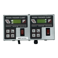
Model - FC-200-2
P/N 121-000-2001
Listed, File No. E183233
Input: 120 VAC, 50/60 HZ.
Double Unit Fuse Sizes:
Unit A = 10 & Unit B = 5 AMPS
Output: 0-120 VAC
80% Duty Cycle at Rated AMPS
© 2009 RODIX
INC.
ELECTRICAL CONNECTIONS:
Make the electrical connections prior to plugging the
control in and turning it on. Once connections are
made to the feeder control, any desired software
settings changes can be made with the cover closed.
1. PART SENSOR
(Photo-sensor or Proximity Switch)
Connect a three wire, current-sinking (NPN) or current-
sourcing (PNP) sensor as shown on the enclosed
wiring diagram. The sensor must be able to operate
on 12VDC and switch 3mA. The default setting is a
universal sensor input.
2. RUN JUMPER INPUT
A Run Jumper is factory installed as shown on the
enclosed wiring diagram.
If the Feeder Cube is to be controlled by a relay
contact, switch or other device, replace the factory-
installed jumper with the controlling "Run Contact" at
terminals 8 and 9 of TB2 (small terminal strip). The
contact must be able to switch 12VDC and 1.0 mA.
The control will then run only when the contact is
closed and the part sensor is calling for parts.
In the High/Low parts sensing mode, a second parts
sensor can be connected to the run contact input in
place of the run jumper. The parts sensor should be a
PNP type and have the same logic (L.O. or D.O.).
3. AUXILIARY OUTPUT
The Feeder Bowl/Hopper Interlock feature (TB2-2 & 3 )
can be connected to a Rodix FC-40, FC-90 or FC-200
Series control when control of a bulk material hopper is
needed. The interlock will prevent the hopper from
operating anytime the bowl is turned OFF or in
"STAND BY" mode. The Interlock output is capable of
12 VDC at 50 mA. The Aux output is capable of
switching 100 mA at 12 or 24VDC if an external power
supply is used. For further information download (or
request from RODIX) the FC-200 Series Advanced
Features Application Note. The Interlock output can
be used to drive a solid state relay that can operate
auxiliary equipment such as an air valve. Two FC-200
Series controls can be interlocked. Download the
FC-200-2 Application Note for wiring information.
A 0.6 Watt 12VDC solenoid can be driven by the
Aux output. Note: a diode must be placed across
the solenoid in reverse polarity to adsorb the
energy when the solenoid is de-energized. Failure
to do so voids the warranty. See the wiring
diagram for proper connections.
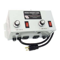
4. LINE VOLTAGE CONNECTIONS
The 120VAC models can operate from a power
line providing from 108 to 132VAC. The plug can
be connected to a standard North American outlet.
The outlet should be properly grounded. The
240VAC models can operate from 200 to 265VAC.
The control should be grounded properly.
5. INTERNAL POWER SUPPLY
At the rated line voltage, the line isolated power
supply is capable of providing a combined total
current of 65 mA at 12 VDC (35 mA when using a
200VAC line on 240VAC models). The total
current includes the parts sensor, CFR sensor and
any auxiliary output accessories that are
connected to the Bowl/Hopper Interlock terminals.
6. OUTPUT CONNECTIONS
The 120VAC models in a general purpose
enclosure provide a standard North American
outlet for connection to the feeder.
7. EXTERNAL SPEED CONTROL
CONNECTIONS
The following methods of remote power level
control can be utilized when desired:
A. The Constant Feed Rate (CFR) feature: Attach
a CFR sensor to terminals TB2-12 (blue) and to
TB2-9 (brown).
B. 4-20mA or 0-20mA signal can be connected by
bringing the positive signal wire to TB2-12 and
ground to TB2-11.
C. 0-5VDC Analog input signal can be connected
to connector H1. This can be selected to
ignore any connections to the CFR/4-20mA
input. Control cable 123-145 sold separately.
Section 13 explains how to enable these features.
FC-200-2.doc 11/16/2009 Page 1