14. LINE VOLTAGE COMPENSATION
Fluctuations in the line voltage can cause a feeder bowl
to vary its feed rate. The line voltage compensation
feature adjusts the control's output to help compensate
for fluctuations in the supply voltage. If it becomes
necessary to disable this feature, the LV Comp setting
can be changed to “Disable”. It is found under “Power
Settings” menu.
15. LIMITING THE MAXIMUM
OUTPUT OF CONTROL
The maximum power (Max Pwr) setting can be lowered
to keep the operators from setting a higher than desired
feeder vibration. The maximum power setting can be
found under the “Power Settings” menu. It can be
adjusted from 100.0% down to 40.0%.
16. POWER SETTING
The output power is controlled by the UP and DOWN
arrow keys. The power setting can be adjusted unless
the security feature lock has been selected. Once the
proper security code has been entered, the power may
be adjusted under the “Power Settings” menu. Note:
the power setting may not be adjusted above the
maximum power setting or below the minimum power
setting level. The max and min power settings
automatically change the power setting to keep it in the
correct range.
17. SETTING THE MINIMUM
OUTPUT OF CONTROL
The minimum power (Min Pwr) output level can be
adjusted to the desired low level of vibration. The
minimum power setting can be found under the “Power”
menu. It can be adjusted up from 0.0% to 60.0%.
Note: the software does not allow the minimum level to
be within 6.4 counts of the maximum level.
18. SETTING THE TIME DELAYS
The ON and OFF sensor time delays are set
independently for a period of 0-25 seconds. The time
delay settings can be adjusted to provide the best
individual response for the feeder. The time delays can
be found under the “Timer Settings” menu.
19. DIAGNOSTICS
A. The first menu item under the “Diagnose Info” menu
shows the software revision level.
B. The next item under the software revision level
shows certain software registers that may be helpful
to Rodix staff while troubleshooting over the phone.
20. SECURITY SETTINGS
The “Security Settings” menu controls access to the
control settings. When enabled, a security code
number may be chosen from 00 to 255. The preset
code is 00.
A. The “Unlock” setting allows menu access for all
control adjustments and features.
B. The amplitude only (Amp Adj) adjustment allows
operators to adjust the amplitude through the
normal operating display. All other settings can
only be adjusted after entering the security code.
C. The “Lock” setting locks the control from any
adjustment without the use of the security code.
If the security code has been forgotten, press the
enter key to bring up the security code. Next, push
and hold the back key until the menu appears. This
sequence bypasses the security code.
21. DEFAULT MEMORY
Occasionally it is helpful to get back to a known
setting. Once a feed system has been set up properly,
it can be saved into the “user default” memory. If an
operator makes wrong adjustments, the “Restore
User” feature can restore the control to a known good
set up. The restore factory defaults selection will put
the original factory settings into memory.
22. LANGUAGE
The programming menus can be displayed in English,
French, German (Deutz), and Spanish (Espanol).
23. INSTALLING THE CFR SENSOR
Note: Failure to adequately prepare the feeder’s
surface properly may result in a Constant Feed Rate
(CFR) sensor that will not bond to the feeder. The
sensor will not be mounted until step C-6.
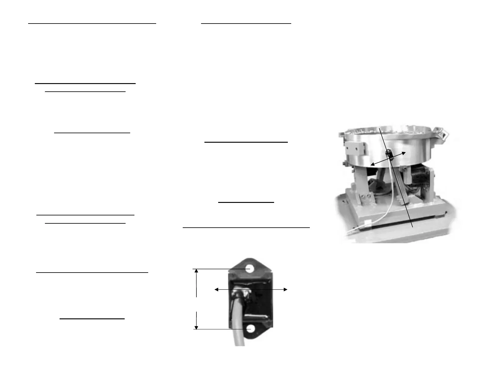
A. ORIENT THE SENSOR so that its sensitive
axis is in the same direction as the vibration of
the feeder. The double-ended arrow in figure 1
shows the sensor’s sensitive axis. Align the
sensitive axis of the sensor in the same direction
as the vibration (see figure 2). The sensor must
be oriented correctly for proper operation.
B. CHOOSE A LOCATION for mounting the
sensor on the feeder that is smooth and that will
allow the adhesive on the sensor to bond. Avoid
mounting the sensor over ridges and bumps which
can reduce the ability of the adhesive to stick to
the feeder. The correct location will also have
enough space for the sensor’s cable to hang
straight down without touching anything else.
Fig. 2 The arrow shows the direction of vibration
which is at a right angle to the spring pack.
C. SURFACE PREPARATION of the feeder is
crucial for proper bonding between the sensor and
the feeder. Please follow these steps completely.
1) The feeder should be kept between 70°-
100°F (21-38°C) for ideal tape application.
2) Clean a 3.5” (10cm) circular area with a
solvent like isopropyl alcohol that will not
leave a residue. As a rule of thumb, the
area can be considered clean when after
cleaning the area with a solvent-saturated,
white paper-towel, the towel is as clean as it
was before wiping.
FC-200-2.doc 10/22/2009 Page 3
Sensitive
Axis of
Vibration
Fig. 1
Actual Size
1.375
Sensitive
Axis of
Vibration
 Loading...