EN
59
6 Description of connections
9TFHHJXXYMJHTSYWTQHTSSJHYNTSYJWRNSFQGTFWIWJRT[JYMJRTYTWHT[JWFXXMT\SNSܪLZWJ
• remove the two screws A and lift the cover (detail B);
• BH30: push the cover in from the side, then lift it up (detail B).
8JJܪLZWJNKYMJGFYYJW^HMFWLJWB71/BC (BH30 Series only) is installed:
• remove the two screws A;
• push the cover in from the side, then lift it up (detail B).
• turn the cover around by 180° (detail C) and set it down in front of the automation system. Warning! Lift the cover
slowly and carefully to prevent damaging the wires.
Figure 3-4-5-6-7-8 shows connection diagrams for connecting mains voltage to the motor control unit (B70/1DC).
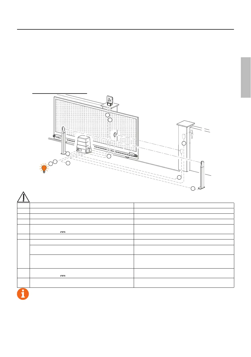
6.1 Typical installation
1
7
8
2
2
6
3
3
4
5
It is the installer's responsibility to verify the adequacy of the cables in relation to the devices used in the
installation and their technical characteristics.
Recommended cable
1 Power supply H07RN-F 3x1,5 mm
2
double insulated cable
2 Photocell - Receiver F4ES/F4S Cable 5x0,5 mm
2
(max 20 m)
3 Photocell - Transmitter F4ES/F4S Cable 3x0,5 mm
2
(max 20 m)
4
LED Flashing light R92/LED24 - FIFTHY/24
Power supply 24V
Cable 2x1 mm
2
(max 10 m)
5 Antenna Cable 50 Ohm RG58 (max 10 m)
6
Key selector R85/60 Cable 3x0,5 mm
2
(max 20 m)
Key pad H85/TTD - H85/TDS
(connecting to H85/DEC - H85/DEC2)
Cable 2x0,5 mm
2
(max 30 m)
H85/DEC - H85/DEC2
(connecting to control unit)
Cable 4x0,5 mm
2
(max 20 m)
The number of conductors increases when using more than
one output contact on H85/DEC - H85/DEC2
7
Gate open indicator
Power supply 24V
3W max
Cable 2x0,5 mm
2
(max 20 m)
8
Courtesy light (Potential free contact)
Power supply 230 V~ (100 W max)
Cable 2x1 mm
2
(max 20 m)
SUGGESTIONS: with existing installations, we recommend checking the cross section of the cables and that
the cables themselves are in good condition.
 Loading...