EN
64
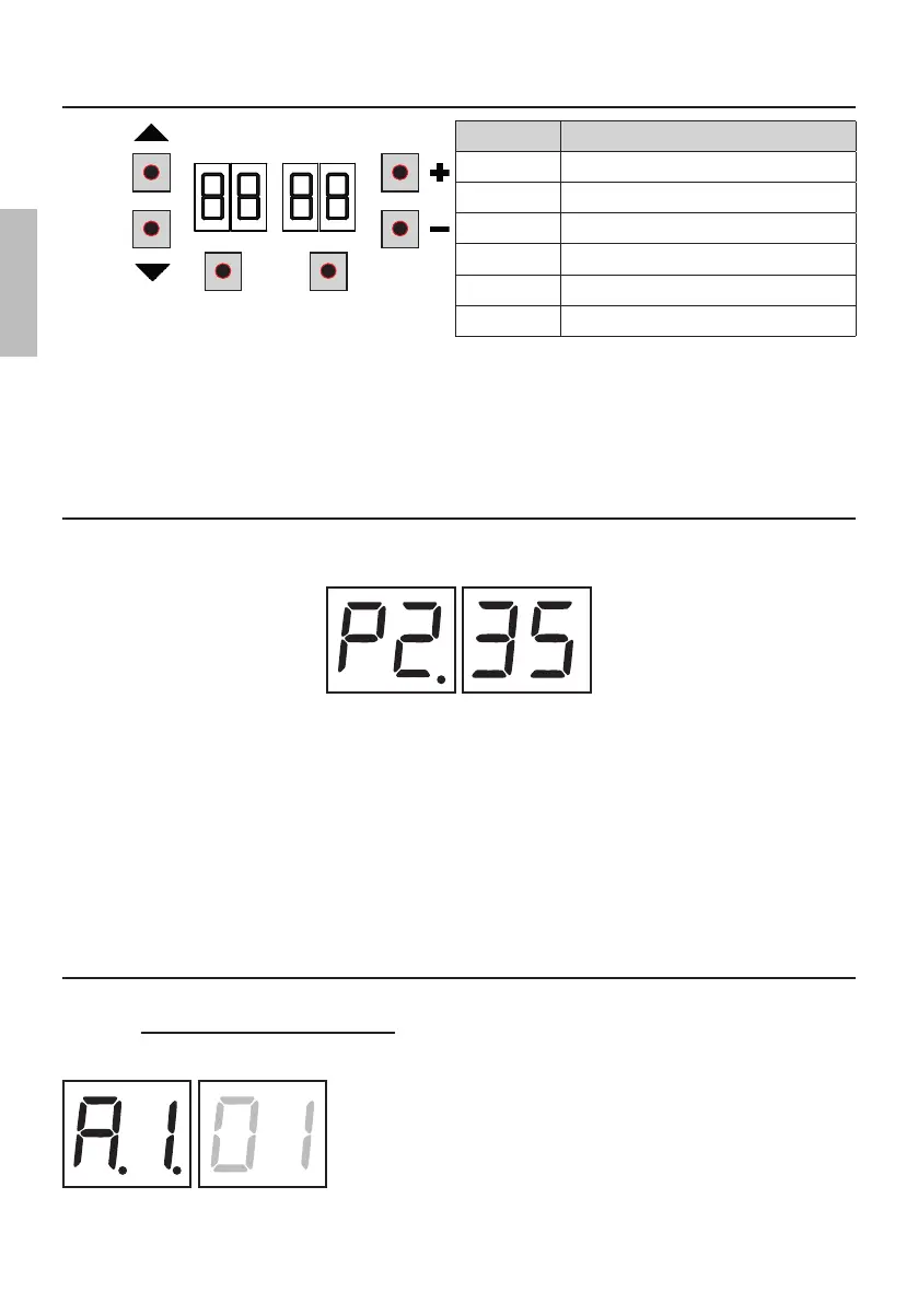
8 Function buttons and display
PROG
UP
DOWN
TEST
BUTTON DESCRIPTION
UP S Next parameter
DOWN T Previous parameter
+ Increase value of parameter by 1
- Decrease value of parameter by 1
PROG Travel acquisition
TEST Activate TEST mode
• Press the UP S and/or DOWN T buttons to view the parameter you intend to modify.
• Use the + and -GZYYTSXYTRTINK^YMJ[FQZJTKYMJUFWFRJYJW9MJ[FQZJXYFWYXYTܫFXM
• Press and hold the + or - button to scroll quickly through values, to modify the parameter more quickly.
• To save the new value, wait a few seconds or move onto another parameter with the UP S or DOWN T button. The
INXUQF^ܫFXMJXWFUNIQ^YTNSINHFYJYMFYYMJSJ\[FQZJMFXGJJSXF[JI
• 5FWFRJYJWXHFSTSQ^GJRTINܪJI\MNQJYMJRTYTWNXSTYWZSSNSL5FWFRJYJWXHFSGJ[NJ\JIFYFS^YNRJ
9 Switching on or commissioning
Power the control unit.
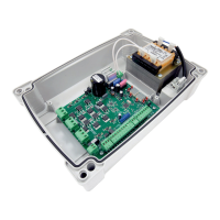
9MJܪWR\FWJ[JWXNTSTKYMJHTSYWTQZSNYNXINXUQF^JIGWNJܫ^
Version installed P2.35.
Immediately afterwards:
• For a control unit mounted on an automation (or supplied with an automation): the display shows the control and
safety status mode (chapter 7)
• For a control unit purchased as a spare part: the display shows "G$W$" and requests initial programming of the
stroke (chapter 11)
In both cases, the execution of stroke programming is mandatory in order to store on the control unit:
• the parameters required for motor control
• the stroke length
ATTENTION!
Failure to carry out stroke programming can lead to serious malfunctions.
10 Display function modes
10.1
Parameter display mode
PARAMETER
PARAMETER
VALUE
See chapter 13 for detailed descriptions of parameters.